PAM4 is a modulation scheme that combines two bits into a single symbol with four amplitude levels as shown in Fig. This effectively doubles a network's data rate, enabling 400G/800G short-haul transmission. NRZ, or Non-Return-to-Zero signaling, represents binary information using two distinct signal levels: This creates relatively wide signal separation between logical states. As a result, NRZ systems historically provided: This operational tolerance helped earlier architectures remain relatively. PAM4 is a branch of the pulse amplitude modulation (PAM) technology, which is a mainstream signal transmission technology following non-return-to-zero (NRZ). Playing a key role in multi-order modulation, PAM is widely used in high-speed signal interconnection. Figure 1-1 shows the typical waveform. A key new modulation scheme, PAM4, was introduced around 2017 and enabled the big jump from 100G to 400G. When it comes to enabling 400G and higher Ethernet speeds, a four-level pulse amplitude modulation or PAM4 multilevel signaling is needed as opposed to the non-return-to-zero (NRZ) modulation.
[PDF]

An Optical Splitter, also known as a beam splitter, is a passive optical device that divides a single input optical signal into two or more output signals. Conversely, it can also combine multiple signals into one. Knowing the difference between a splitter and an optical coupler helps you build better networks. You make your network work better when you pick the right device for each job. You can connect many users to one port with 1:n or 2:n splitters. By dividing a single optical signal from a central Optical Line Terminal (OLT) into multiple outputs for Optical Network Terminals (ONTs) at users' homes, splitters eliminate the need for dedicated fibers to each residence—slashing infrastructure costs while scaling network reach. This guide. In a Passive Optical Network (PON), a single optical fiber carries massive amounts of data using light. Signal Input: The fiber splitter receives the optical signal from the upstream network node and enters the splitter through the input fiber. Signal Distribution: Inside the splitter, according to the design structure and different. Splitters are passive optical devices that divide or combine optical signals, and they come in various types, including power splitters, uneven splitters, and wavelength-division multiplexing (WDM) splitters. Each type serves specific applications, enabling efficient use of optical infrastructure.
[PDF]
An optical modulator is a device which can be used for manipulating a property of light — often of an optical beam, e. Depending on which property of light is controlled, modulators are called intensity modulators, phase modulators, spatial light modulators, etc. The beam may be carried over free space, or propagated through an optical waveguide (optical fibre). This lets devices send lots of data fast and without mistakes. This process dynamically alters properties of an optical carrier wave—such as amplitude, phase, frequency, or polarization—to embed data. These devices play a crucial role in modern optics and photonics, enabling the manipulation of light for various applications. An optical modulator is a critical component in the realm of photonics and optical communications, playing a pivotal role in manipulating light to encode. Optical modulation allows one to control an optical wave or to encode information on a carrier optical wave. The inverse process that recovers the encoded information is demodulation. According to the.
[PDF]
The system in this example contains the following elements: 1. 2 Pseudo-random Bit Stream (PRBS) block 2. 2 NRZ Pulse Generator (NRZ) 3. 1 CW Laser (CWL) 4. 3 1x2 Fork (FORK) 5. 2 Electrical Not Gate (N.
[PDF]
Filter your results below. The Marvell® PAM4 optical DSP portfolio, including Spica™ and Nova™ DSPs, addresses the critical the need for high-bandwidth optical interconnects to power AI infrastructure. Marvell leads the pluggable module ecosystem with low-power, high-performance silicon for AI, cloud, enterprise and 5G. MaxLinear's highly integrated PAM4 DSPs offer superior link-margin performance and low power to enable 100G, 400G, 800G, and 1. 6T optical interconnects inside the data center. DCP-M is a genuine open line DWDM platform, specifically engineered for contemporary DCI. While it possesses the form factor and user-friendliness of a passive multiplexer, DCP-M stands out by actively monitoring traffic, amplifying signals for extended distances, and accommodating higher data rate. In this context, the 100G DWDM PAM4 optical module, which combines the advantages of PAM4 modulation and DWDM technology, becomes an ideal solution. This article will explore the definition, features, advantages, application scenarios, and FS product highlights of 100G PAM4 DWDM optical modules. Watertown, CT – The Siemon Company, a global leader in high‑performance network infrastructure solutions for data centers and smart buildings, is proud to announce the launch of its portfolio of 200G, 400G, and 800G PAM4 high‑speed optical transceivers, expanding Siemon's end‑to‑end data center. DCP-M is a true open line DWDM platform designed specifically for modern DCI.
[PDF]

This article provides a detailed technical comparison between fiber optic and copper cables, offering a clear perspective for engineers, network architects, and procurement managers. The core distinction between the two technologies lies in the physics of data. There are significant differences in performance between ADSS cables (all-dielectric self-supporting optical cables) and traditional optical cables, which are mainly reflected in the following aspects: 1. This type of fiber optic cable is designed to support its own weight without the need for additional support structures like messenger wires. The ADSS. There are several factors to assess when deciding which cable type is right for your application, including speed of connection for new customers, ease of changes and repairs, installer certification requirements, and the ability to expand the network over time. ADSS Fiber Optic Cables are a type of optical fiber cable designed specifically for. All-dielectric self-supporting (ADSS) cable is a type of optical fiber cable that is strong enough to support itself between structures without using conductive metal elements. It is used by electrical utility companies as a communications medium, installed along existing overhead transmission.
[PDF]

Per‑unit estimates often appear as $0. 50 per ft for basic fiber plus additional charges for trenching and install labor. Several drivers shape fiber installation pricing. Homeowners and businesses typically pay for fiber optic cable installation based on distance, conduit needs, and labor. The main cost drivers include material type, run length, trenching or aerial work, and any required permits or inspections. This guide provides clear cost estimates, price ranges. The initial cost of installing fiber optic cables can vary depending on the chosen installation method and specific project requirements. Total Project Costs: For commercial installations, expect costs ranging from $5,000 to $20,000 per mile for underground projects and from $40,000 to $60,000 per. Buyers typically pay for fiber laying by combining material costs, labor time, and permitting plus trenching or aerial support fees. A short residential drop under 1,000 ft may cost $3,000-$8,000, while longer runs to an attached garage or street node can run $8,000-$25,000. The price often reflects project scope, geography, and local regulations, making. Fiber optic cable costs vary widely – from $0. Installation can be more expensive than the cable itself, especially with site challenges.
[PDF]

This report covers the optical, environmental, and mechanical performance of the LC-UPC, singlemode fiber optic BOAs, provided by Tyco Electronics, Fiber Optics Business Unit. Qualification testing was completed by a third party in July 2004. IDEAL FOR DEBUGGING OPTICAL POWER PERFORMANCE & OPTICAL INSTRUMENT CALIBRATION CORRECION & FIBER SIGNAL ATTENUATION. As optical passive devices, FS attenuators are mainly used in fiber optic to debug optical power performance & optical instrument calibration correction & fiber signal. L-com offers an extensive line of dual wavelength (1310/1550nm) Singlemode fiber optic attenuators. These versatile in-line attenuators are the perfect solution for attenuating Singlemode fiber connectors for both lab and commercial applications. Constructed of the highest quality materials and. zation system's perfo. the power of an optical signal. Our LC/APC single mode attenuators can handle a maximum o 1 watt of optical input power. This device contains one ale and one female LC/APC port. LC/APC optical attenuators can be ordered in attenuation. Fixed loopback type attenuators from OMC offer defined control of optical signals in both integrated and add-on products. Depending on the project or need, fixed attenuators can limit (attenuate) the amount of light passing through to the exact levels your project or application requirement.
[PDF]

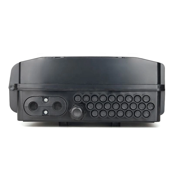
Run the display transceiver [ interface interface-type interface-number | slot slot-id ] [ verbose ] command to view information about the optical module on a specified interface. In optical communication equipment, an optical module (Optical Module) contains several types of semiconductor chips that work together to complete the transmission and processing of optical signals. These chips typically include laser chips, photodetector chips, driver chips, transimpedance. When the optical module on an interface is faulty, you can run the display commands to view information about the optical module. Today, we will deeply analyze the four mainstream models of 100G QSFP28 dual-fiber optical modules: QSFP28-100G-SR4, QSFP28-100G-LR4, QSFP28-100G-ER4 and. The following uses the Moduletek SFP-10G-LR module connected to a Huawei S6700 switch as an example to introduce how to read information of the connected optical module on a Huawei switch. Figure 1 Schematic Diagram of Optical Module Connected to Switch 1. Optical Module Status Check Run the. Upgrade to 100G or 400G optics and save. Cisco Transceiver Modules - Learn product details such as features and benefits, as well as hardware and software specifications. Network administrators have a major challenge determining the right Cisco SFP modules, understanding complex model numbers that directly affect network performance and stability.
[PDF]

Explore 74 top manufacturers and suppliers of Optical Testing Instruments in our comprehensive photonics buyers' guide. An optical testing instrument is a device or system used to evaluate and measure the performance, quality, and characteristics of optical components. Source Photonics, founded in 1988 and based in Los Angeles, California, is a technology company that specializes in optical transceivers and data connectivity solutions. The company provides a wide range of products tailored for data centers, broadband, and optical transmission, serving. CACI designs and manufactures optical communications terminals for all of the major orbits in which our customer missions operate. These bespoke solutions are being manufactured in Orlando at CACI's space manufacturing and testing facility, which opened in June 2022. The facility is dedicated to. Manufacturer of standard and custom opticaltestequipment including microscopes, pocket comparators, disc gages, grids, scales, strips, slits, and micrometers. Suitable for optical, gaging, imaging, and calibration applications. Serves aviation industry. Lapmaster Wolters is estimated to have. Optical transceivers are devices that convert electrical signals into optical signals for transmission and reception. They are primarily used in communication systems that employ optical fiber cables, serving the purpose of signal conversion between the transmitting and receiving ends.
[PDF]

The optical module is usually composed of Transmitter Optical Subassembly (TOSA, containing a laser LD Chip), Receiver Optical Subassembly (ROSA, containing a photodetector PD Chip), a driving circuit, and an optical and electrical interface. Its schematic is shown in. This section explains the structure of a typical pigtail butterfly module, which gets its name from the two rows of seven leads at right angles on each side of the metal package plus an optical fiber pigtail at one end (Fig. Let's look at the internal structure (Fig. 2) of a common butterfly. Optical modules are devices used to connect network devices, transmit and receive data between network devices, and can be used to convert optical and electrical signals. The optical module is a very important component in an optical communication system. Optical devices are the core components of optical modules. TOSA and ROSA in Common Optical Transceiver Modules For ordinary optical transceiver modules, there are two optical devices, TOSA and ROSA, which have opposite effects.
[PDF]

FS optical line protection switch features 1+1 backup and less than 15 ms fast switch to the standby fiber link that ensures business uninterrupted when malfunction occurs. An optical protection switch is a critical component in fiber optic communication systems designed to safeguard optical signals and infrastructure from damage due to power surges, signal overloads, or system failures. These switches ensure signal integrity, minimize downtime, and enhance network. 1+1 Optical Line Protection System for Fiber Protection, Bi-directional Protection in Dual Fiber, LC/UPC, Pluggable Module OLP (Optical Line Protection) is a device used in pairs, one at each end of the optical signal to protect network transmission line. OLP products include fiber optical line protection switches, optical bypass switches, optical cross connection, multi-channel. The FOSW-1x1 or 1x2 optical switch is based on opto-mechanical technology with proven reliability. OSW-W1x2 optical switch is a high performance electro-optical device, with low insertion loss (typic. In optical communication network, OLP monitors optical power of optical fiber and standby.
[PDF]
Here at AFL we provide years of experience and excellent solutions for your hardware needs in both ADSS (All-Dielectric Self Supporting), OPGW (Optical Ground Wire) and SkyWrap cables. Please follow the links below for assistance in choosing your hardware. The aluminum Opti-LoopTM FOS for All Dielectric Self Support (ADSS) cable is available in 3 sizes. With more than one million units in service, Opti-Loop fiber storage systems lead the industry in quality and durability. All aluminum construction with continuous welds at crossbars and ends. Each. Also see our line of ADSS Fiber Optic Cable. © Copyright 2026 AFL. Our product experts are here to assist you. Get in touch with our team now. PLP transmission, distribution, substation, fiber optic, solar, and EV solutions protect and connect overhead electric power lines and communications networks. ADSS Anchor Tension Clamps are hardware fittings used to securely terminate and anchor ADSS fiber optic cables on poles or towers without damaging the cable. This is a type of self-supporting optical fiber cable that does not require any kind of support in distributing electricity from one point to another. As much as they may be independent, these cables are usually installed on poles and.
[PDF]
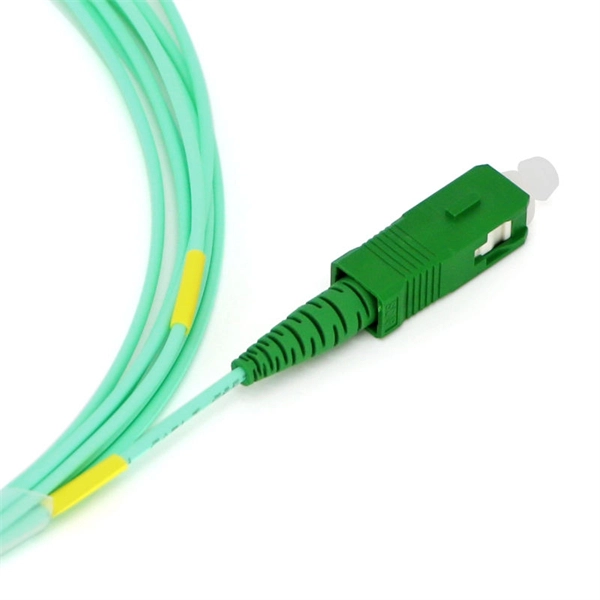
With protective doors, dust-proof 2). Suitable for many types of modules, used in cabling work area subsystem 3). Embedded type surface, easy for installation and removal 4). Available for fiber optic SC simplex or LC duplex and can be used in both surface mounted. 1). This termination box supports 0. 0mm pigtails and 2x3mm indoor drop cables. Discover the Welink FTB-1005: a high-quality 1 Core Fiber Optic Outlet for FTTH. RoHS certified, compact, durable, and easy to install. Compact Design: Space-saving footprint (86x86mm) ideal for residential and office wall mounting. Splice Protection: Integrated tray securely holds fusion. FTTH Terminal box is a compact fiber terminal for use at the final fiber termination point in the customer premises. It provides mechanical protection and managed fiber control in an attractive format suitable for use inside customer premises, A variety of possible fiber termination techniques are. 1 Core Fiber Optic Desk Terminal Box for SC, FC Adapter, Patch Cord or Pigtail Description: 1). It provides a secure and convenient location for fiber optic splicing, connecting the drop cable and the passive optical equipment of the optical network. protection and management for the FTTx network building. Features: Scope of application 3. Specification: Applications: 1 Core Fiber Optic Terminal Box is used as a termination point for the feeder cable to connect with drop cable in FTTx communication network.
[PDF]
Glass fiber and plastic fiber is fragile. When individual fibers break, light transmission and uniformity are reduced. After the first few fibers break at a stress point, a chain reaction occurs, hastening t.
[PDF]