Connecting fiber optic cable directly to a standard Ethernet port is not possible. Ethernet ports are designed for copper cables (like Cat5e or Cat6), which transmit data using electrical signals. The process to connect fiber optic cable to router requires careful attention to detail, but I'll walk you through every critical step with the precision and clarity you deserve. This comprehensive guide combines industry standards with field-tested practices to ensure you achieve a rock-solid. In this guide, we'll walk you through how to connect a fiber optic cable to a router safely and efficiently. Why Use Fiber Optic Internet? Before diving into the setup, let's quickly recap why fiber optics are worth the effort: Lightning-fast speeds (up to 1 Gbps or higher). Here's a step-by-step guide to help you through it. Check compatibility: Before you begin, make sure your router supports fiber optic connection. Not all routers can connect directly to a fiber cable, so it is important to verify this information before continuing. Gather. Unlike regular electrical wires, these glass fibers can snap or bend too far. Proper connectors, clean ends, and a good splice keep everything sharp and stable. When you connect the fiber optic cable correctly, you keep your fiber internet, ONT (optical network terminal), and router running at peak. Connecting a fiber optic cable to a router involves a few key steps and specialized equipment.
[PDF]
Den här guiden går igenom allt du behöver känna till när du vill koppla din egen router till fiber, vilka alternativ som finns, vilka inställningar som krävs och hur du felsöker om något inte fungerar som det ska. However, setting up a fiber optic connection to your router can seem daunting if you're unfamiliar with the process. In this guide, we'll walk you through how to connect a fiber optic cable to a router safely and efficiently. Why Use Fiber Optic Internet? Before diving into the setup, let's quickly. Setting up a fiber internet connection requires understanding key hardware components and following a specific connection sequence to establish your home network. This comprehensive guide combines industry standards with field-tested practices to ensure you achieve a rock-solid.
[PDF]
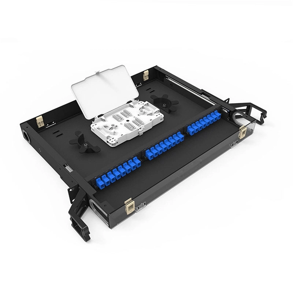
How to install a fiber optic cable into a patch panel. Fibre Optic Patch Panel Installation Fibre Optic Cabling Know How - how to connect Fibre Optic Cable to a Patch Panel This video shows you how to install. Fiber optic patch panel is a crucial component in optical communications networks. It also known as a fiber patch panel or fiber distribution panel. It serves as a central point for organizing, managing, and connecting fiber optic cables. At its core, a fiber optic patch panel acts as a hub for. What are the best practices for fiber patch panel installation? The best practices below help to avoid installation issues and ensure ease of service for the system. Penetrate the enclosure from the side or bottom to minimize the risk of water intrusion. Step 1: Gather the Tools and Equipment The first step in connecting. How to Install a Fibre Optic Cable into a Patch Panel ( Fibre Optic Patch Panel ) How to install a fiber optic cable into a patch panel. This is essential for streamlining network. Running fiber internally involves extending this high-speed link from the service entry point to a centralized location, such as a dedicated media closet or network rack. This DIY effort is undertaken to maximize performance, improve aesthetics, or relocate the Optical Network Terminal (ONT) to a.
[PDF]

NOTE: Insert the end of a colored wire into one of the holes in a butt connector. With the wires pushed tightly against the far inside wall of the connector, squeeze the red button until it depresses. The OS-8171 Beam Splitter is designed to be used with the OS-8170 Brewster's Angle Accessory and the OS-8539 Educational Spectrophotometer System. ) In the Brewster's Angle experiment, the Beam Splitter is used with a. am Splitters/Combiners. This document describes this product line, as well as general operation guidel into two output beams t beams of equal power. The standard product is designed for use in the visible spectrum 400-700 nm wavelength). Custom Surgical Beam Splitter sends 50% of the light to the eyepieces and 50% to the smartphone camera. If you want to understand more about how beam splitter works, watch the video below. It is not necessary to. As title. in your towing vehicle manual. Be sure the hitch is installed onto the vehicle. Releasing the pin before will cause supp owards the engine faster than you can let go. This is because if a fire. Meadowlark Optics presents its VersalightTM wire grid polarizing beam splitters. Manufactured for wavelength ranges between 420 and 2600 nm, this polarizer is ideal for broadband and wide field-of-view applications. Wire grid polarizing beam splitters are manufactured out of our Versalight wire.
[PDF]

This is the most fundamental ring topology, formed by connecting three or more switches in a closed loop using fiber optic cables. Data can flow in either direction, allowing the network to recover quickly if a link fails. If you have multiple Ethernet switches that need to be connected over long distances, fiber is obviously a preferred choice. Moreover, when it comes to bandwidth, no currently available technology is better than single-mode fiber. It can provide significantly higher bandwidth and carry more data. A single 6 strand fiber can only connect 3 switches back to the core. How many switches do you plan to connect? A star is great for a limited number of switches. I have maybe 20 coming back to my cores. Rings are generally not done anymore, but I think that is for bandwidth as much as anything else. The mainline of the fiber optic LAN directly connects to the switch, then to the router. The connection between two or more Ethernet switches in a certain way (Uplink port, etc. ) is called the cascade. All switches have two fiber ports. Is the best way to have fiber backbone switch and connect fiber channel from every switch to the backbone? Or connect switch 1 to switch 2 to switch 3 to. switch 12 to switch 1 again? Thanks! Let's get some. I need to connect 4 Floor Building with 4 Cisco 2960 - 48 ports switch each other and it needs to be through a fiber. This design ensures data can travel in both directions.
[PDF]

This comprehensive guide will explore the importance and benefits of this integration, provide an understanding of fiber optic cable and Ethernet ports, discuss their compatibility, and offer a step-by-step process for connecting them. Proper connection of fiber optic cables is essential to harness these benefits fully, as even minor errors can lead to significant performance issues like signal loss. This article will guide you through the necessary tools, materials, and methods on how to connect fiber optic cables effectively. Using an optical cable involves connecting it to the right equipment, ensuring proper installation, and testing the system for optimal performance. Here's a step-by-step guide on how to use optical cable effectively: 1. Check Compatibility of Equipment Ensure that your equipment (e., network. One powerful solution to achieve these goals is by connecting fiber optic cables with Ethernet ports. This comprehensive guide combines industry standards with field-tested practices to ensure you achieve a rock-solid. These transceiver modules are hot-swappable input/output (I/O) devices that plug into 100BASE, 1000BASE and 10GBASE ports (for SFP+), which connect the module port with the fiber-optic or copper network. The SFP transceiver modules are hot-pluggable I/O devices that plug into module sockets. The number one cause of signal loss in optical fiber installations is dirt on.
[PDF]

In this video, we'll show you how to connect an energy meter to a distribution board (DB) safely and efficiently. energy meter connection with distribution box How to Connect an Energy Meter to Your Distribution Box Easily Steps to Properly Connect Your Energy Meter to a Distribution Box. It plays a vital role in ensuring the safe and efficient distribution of electricity throughout the premises. What is the wire from the meter to the breaker box? Also. Always begin with disconnecting the main supply before accessing any enclosure containing distribution components. This prevents arc faults and ensures safety when modifying or inspecting current paths. This “meter to panel” wiring establishes the pathway for all incoming electrical power from the grid to the home. Its primary function is to safely and reliably. Distribution Board aslo know as “Panel Board”, “Switch & Fuse Board” or “Consumer Unit” is a box installed in the building containing on protective devices, such as circuit breaker, fuses, isolator, switches, RCDs and MCBs etc. The electric main supply (230V AC & 120V AC in US) is connected through. Changed Texas's reference diagram for the 3 wire network 120/208 Volt single phase self-contained Revised Figures 13, 14, 14b. Limited the meter location from pad mount transformer for PSO. Removed unistrut being listed as an alternative means for mounting the meter box. APCo and TX do not allow.
[PDF]
In this ultimate guide, I'll break down exactly what QSFP cables are, how they compare to SFP and SFP+, how to choose the right type, installation and maintenance best practices, and the real benefits you can expect. What is a QSFP Cable?. The Cisco 100GBASE Quad Small Form-Factor Pluggable (QSFP) portfolio offers customers a wide variety of high-density and low-power 100 Gigabit Ethernet connectivity options for data center, high-performance computing networks, enterprise core and distribution layers, and service provider. The Quad Small Form-Factor Pluggable (QSFP) family represents a critical evolution in high-speed optical transceiver technology for data centers, telecommunications networks, and enterprise infrastructure. It interfaces a network device motherboard (for a switch, router, media converter or similar device) to a fiber optic cable. It is. Among the most widely used are the Small Form-factor Pluggable (SFP), its faster counterpart SFP+, and the high-capacity Quad Small Form-factor Pluggable (QSFP). These compact yet powerful devices are foundational to modern networking, offering diverse options for bandwidth, range, and application. annels of data in one pluggable interface. Each channel is capable of transferring data at 10Gb/s and support a total of 40Gb/s as specified for QSFP+. These interconnects have thr e times the density of SFP+ interconnects. The QSFP product family includes cages in single and ganged configurations.
[PDF]

The Gateway Cities Council of Governments' (GCCOG) Gateway Cities Fiber Optic Network Project will expand fiber optic infrastructure, aiming to establish a new regional fiber network to address the digital divide and provide high-speed internet access. The FOA created its Online Reference Guide to provide a more up-to-date and unbiased reference for those seeking information on cabling and fiber optic technology, components, applications and installation. It's success confirms the assumption that many users prefer the Internet for technical. Building a fiber optic network is a highly technical yet vital process that enables communities and businesses to access high-speed, reliable fiber optic internet. From the initial site survey to the final fiber to the home (FTTH) connection, every stage requires careful planning, coordination, and. Fiber optic network design is not simply a theoretical framework—it is a disciplined engineering process that determines how infrastructure will perform, scale, and be maintained over the next 20 to 30 years. The project involves building significant.
[PDF]

Insert the end of your fiber optic network line into the fiber optic connector on the converter box. Plug an Ethernet cable into the Ethernet port on the converter box and plug the other end into one of the Ethernet ports on the back of your Ethernet switch. As we speak I just have optic fibre (Community Fibre) connected to my Huawei modem / Linksys Velop which will be connected to a new POE switch (need to identify the best model to be compatible with my optic fibre extension project). The objective is to run 1 or 2 additional optic fibre from the. Connecting a fiber optic switch involves several steps, ensuring compatibility between the switch's ports and the fiber optic cable. Fiber optic switches utilize. Fiber optic cabling is increasingly used to connect network switches and other datacom equipment, especially in long-distance and mission-critical applications. Fiber provides: Increased internet signal bandwidth. Advantages Determine the length of the fiber run and choose either multi mode for runs under 1000 feet or single mode for runs over 1000 feet.
[PDF]
This beginner-friendly guide will walk you through the step-by-step process of fiber optic cable installation for each method, highlighting best practices, tools, and considerations. Proper connection of fiber optic cables is essential to harness these benefits fully, as even minor errors can lead to significant performance issues like signal loss. This article will guide you through the necessary tools, materials, and methods on how to connect fiber optic cables effectively. Starting with site surveys and permissions, to installing fiber optic cable and emphasizing the process as a key stage in mastering fiber optic installation, to the careful handling of cables and high-stakes splicing, each stage is critical. Discover the exact steps, adhere to stringent safety. Single family homes, apartments, condominiums and other multi-dwelling units are increasingly wired with fiber optic cable to future-proof installations and create more reliable, higher-bandwidth and faster speed network and video infrastructures. The processes. Running fiber internally involves extending this high-speed link from the service entry point to a centralized location, such as a dedicated media closet or network rack. This DIY effort is undertaken to maximize performance, improve aesthetics, or relocate the Optical Network Terminal (ONT) to a.
[PDF]

When you connect two 1000BASE-T switches with SFP ports to achieve Gigabit Ethernet, there are two methods: through standard Ethernet cable plugged into the built-in Ethernet ports of each switch, or use the SFP ports with a copper SFP module. 🎥 In this video, I show you how to connect two different branded switches using SFP modules and fiber optic cables. Whether you're using Cisco, Planet, TP-Link, D-Link, Ubiquiti, or any other brand — the key is understanding SFP compatibility. Before moving ahead, let us discuss some basics about standard Ethernet cables and 1000BASE-T (IEEE 802. Network topology refers to the way in which the links and nodes of a network are arranged in relation to each other. What Is a 10Gb SFP Module? A 10Gb SFP (Small Form-factor Pluggable) module is a compact, hot-swappable transceiver used to establish high-speed fiber. Did you swap one of the fiber connectors at one of the endpoints? Meaning, take off the housing of the fiber connector, and swap a and b. You'll find SFP / SFP+ specs on the datasheets for the switches. They're free to view and download from Cisco. Cisco also publish a GBIC /. Most modern fiber-enabled network switches require an SFP transceiver module featuring a duplex (two strand) multimode OM3 or duplex single mode OS2 connection with LC connectors. Direct attach cables with pre-terminated SFP connections may also be used. Download the Application PDF SFP transceiver.
[PDF]

Use the SWD or JTAG interface to connect the ST-Link v2 to the STM32 microcontroller. Download and install STM32CubeIDE or another compatible IDE. Install the ST-Link USB driver (available on the STMicroelectronics. The ST-LINK/V2 is an in-circuit debugger/programmer for the STM8 and STM32 microcontrollers. The single wire interface module (SWIM) and the JTAG/serial wire debugging (SWD) interfaces facilitate communication with any STM8 or STM32 microcontroller operating on an application board. ATOLLIC, IAR and KEIL Integrated Development Environments for. How do you use SWD (Serial Wire Debug) for debugging STM32? - HackMD Using SWD (Serial Wire Debug) for debugging STM32 microcontrollers is a powerful way to monitor and control code execution, inspect registers, and analyze faults. Here's a step-by-step guide to set up and use SWD effectively: 1. In addition. This small guide will explain how to connect your debugger to your development board. There are two commonly used connectors which expose only the SWD (Serial Wire Debug) interface or the full JTAG interface. If you are using one of ST's official Nucleo or Discovery boards, you do not have to. To upload a program to a chip from Thomson Semiconductor you need an ST-Link programmer device to connect your PC. Thompson sells branded programmers, adaptors and cables. We'll use an inexpensive ST-LinkV2. They look like AVR programmers but you need to read the pinouts on the side.
[PDF]

This guide details the necessary physical and digital steps to connect your fiber line and activate your internet service. The fiber optic cable does not plug directly into a standard home router because the signal type must be translated. Fiber optic networks are celebrated for their speed and reliability, but even the best systems can encounter problems. When issues like signal loss, slow speeds, or intermittent connectivity arise, systematic troubleshooting is key. This guide will walk you through diagnosing and resolving common. Fiber optic troubleshooting is the systematic process of identifying, diagnosing, and resolving problems within fiber optic communication networks. These networks are the backbone of modern data transmission, offering incredible speeds and bandwidth. However, even the most robust systems can. When your fiber optic network stops working, begin with a structured approach. First, check the basics—look for power issues on your optical network terminal and inspect all cables for visible damage. Many fiber internet problems come from dirty connectors or loose plugs, not major faults. The fiber line terminates at the Optical Network Terminal.
[PDF]
Learn how to splice fiber optic cable using fusion splicing with this complete step-by-step guide. Includes tools, best practices, loss standards (ITU-T G. 652), cost analysis, and FAQs for network engineers and installers. Splicing fiber optic cable is an extremely important phase for making dependable, high-speed communication infrastructures. Regardless of the type of fiber network you're deploying, be it for telecom, enterprise data centers, or smart city infrastructure, fusion splicing provides the benefits of. Proper connection of fiber optic cables is essential to harness these benefits fully, as even minor errors can lead to significant performance issues like signal loss. This article will guide you through the necessary tools, materials, and methods on how to connect fiber optic cables effectively. Previous video we explain how to do splicing of fibers optic cable in joint closure. this video are showing how to arrange sleeves in the cable tray and arrangement of fibers. Before connecting any fiber cable, you need to assemble the proper preparation tools: With the right tools in hand, follow these key steps to achieve reliable fiber connections: 1. Strip and Clean Fiber Ends. Fiber optic internet delivers blazing-fast speeds and reliable connectivity, making it a top choice for modern homes and businesses. However, setting up a fiber optic connection to your router can seem daunting if you're unfamiliar with the process.
[PDF]
