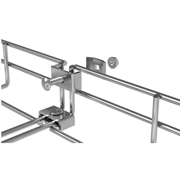
This standard outlines the construction requirements, testing methods, and performance parameters for cable trays and related support systems. As one of the best Cable Tray Manufacturers in Madagascar, we are trusted by people not only within the boundaries but even beyond that. Our custom-based products are able to match up your distinct needs. Whether you're designing a new facility or upgrading an existing electrical infrastructure, understanding and applying the IEC standard for cable tray is. us-trations without notice. All illustrations, descriptions and technical information included in this document are provided as indications and can cable trays are equivalent. The mechanical and electrical characteristics, tests, certifications, overall quality management, recommendations mentioned. Not all cable trays are equivalent. IEC 61537 covers cable tray and cable ladder systems for the support and accommodation of cables, while NEC Article 392 governs cable. We, one of the well-known Cable Trays Manufacturers in Madagascar, offer top-notch trays that keep your electrical system organized and protected. Our durable, high-quality trays come in various sizes and styles to fit any project, big or small. Our robust trays safeguard your cables from physical.
[PDF]
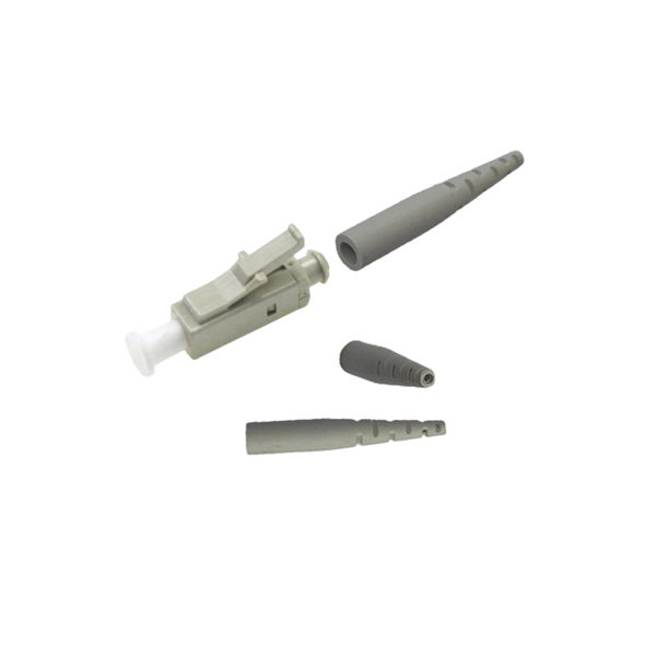
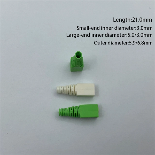
Fiber optic connectors are the backbone of high-speed data transmission, but choosing the right interface—SC, LC, or MPO—can make or break your network's efficiency. In this head-to-head comparison, we analyze their size, port density, performance metrics, and ideal use cases, backed by data charts. They use precision ferrules and alignment sleeves to connect two fiber cores, maintaining light transmission efficiency. Because of this, it's no surprise that fiber optic connectors are in high demand across several industries. Their primary function is to precisely align the end faces of two optical fibers via an intricate mechanical structure to minimize optical signal transmission loss. The basic structure includes components such as. Fiber optic connectors are essential components in optical communication systems, enabling quick and stable connections between fibers. They are. LC, SC, FC, ST, MPO/MTP compared: ferrule sizes, polishing types, insertion loss, and a decision flowchart to choose the right fiber connector for your application. This allows for quickly connecting and disconnecting of fiber optic cables without splicing. The connector features a ferrule, the connector end piece that holds and secures the fiber and aligns it for light.
[PDF]

Key finding: This paper develops analytical models and design procedures of ultra-wideband Wilkinson power dividers using linearly tapered transmission lines (TTLs) which provide size reduction and broadband performance. Read more. Power dividers are the passive electronic equipment used for splitting the power. They are now being employed in a variety of communications applications such as telephonic, antennas configurations, mobile connectivity, internet technology, & optics, etc. They come up with very low loss, operate at. RF and microwave power splitters and dividers create two copies of the same signal, while ideally preventing crosstalk between the outputs. Doing this with minimal loss while maintaining signal integrity is a challenge. In this article we explain how power splitters work and what the tradeoffs are. The rise of wireless connectivity requirements for applications such as Internet of Things (IoT), cellular, and automotive electronics is resulting in systems that are increasingly using RF signals, components, and subsystems. Often, designers need to direct these signals to more than a single. A power divider is a passive electronic device used in radio frequency (RF) and microwave applications to split an input signal into multiple output signals with equal or specified power levels, while maintaining impedance matching to minimize signal reflection and loss. How can power dividers.
[PDF]

This report describes a set of five field evaluations conducted by Pacific Northwest National Laboratory (PNNL) and DesignLights Consortium for U. Department of Energy, between November 2015 and September 2017, to demonstrate the potential energy-savings capability of advanced . Lighting systems define the difference between a toy grade machine and a professional-grade scale crawler. Choosing the right controller dictates how that light behaves, moving beyond simple on-off switches into the realm of true scale realism. Integrating these systems transforms a static rig into. What Defines a Great Lighting Control System in 2025? 1. Lutron (Vive & Quantum): The Scalable Market Leader 2. DALI (Digital Addressable Lighting Interface): The Open Protocol Standard 3. Crestron: The King of High-End Integration 4. Casambi: The Leader in Bluetooth Mesh Wireless Control 5. PoE. These systems provide a consolidated method for managing all of your home's lights using a single app or device. However, choosing from the wide range of available options might be challenging. To assist you in making a wise choice, we have put together a guide to the top home lighting control. re being properly set up and tested for the Program Administrators (PAs). These criteria will ease the decision-making around the appropriate savings factors and incentive levels that projects can claim. By combining technical parameters with hands-on project experience, it supports designers.
[PDF]
This article will deeply explore the unique charm of optical circulators from five aspects: the forefront of technological innovation, efficient cyclic transmission, wide application fields, excellent and stable performance, and future development prospects. Frontier of. An Optical Circulator is a non-reciprocal device that routes light from one port to the next, in a unidirectional manner. This unique device has broad applications in many fields, from optical telecommunications to fiber-optic sensor systems. They are crucial components in modern optics and photonics, enabling the efficient routing of optical signals. The basic principle of an optical. The evolution of optical circulators can be traced back to the advancements in fiber optics technology during the late 20th century, which necessitated the development of devices capable of managing complex light pathways. They are technically related to Faraday isolators, and on a broader scale similar to electronic circulators.
[PDF]
This study is focused on the detailed examination of the combustion properties and kinetic analysis of a cellulose acetate fibrous bundle (CAFB), separated from used cigarette filters. Introduction Cigarette butts are the most common garbage lying in city streets, restaurants, bus stops, parks, and other public places. Although cigarette butts are small, they are. Fiber Bundles and more general fibrations are basic objects of study in many areas of mathe-matics. A fiber bundle with base space B and fiber F can be viewed as a parameterized family of objects, each “isomorphic” to F, where the family is parameterized by points in B. For example a vector bundle. In this paper, we introduce RBPseg, a method that combines monomeric 23 ESMfold predictions with a novel sigmoid distance pair (sDp) protein segmentation technique. These segments are then predicted in parallel using AF2M and assembled into a 26 full fiber model. We demonstrate that.
[PDF]
Optical pulses traveling through multimode optical fibers encounter the influence of both linear disturbances and nonlinearity, resulting in a complex and chaotic redistribution of power among different modes. I.
[PDF]
Whether you're installing new fiber optic cables or troubleshooting and repairing an existing fiber network, a working knowledge of the regulations that apply to your project can help you (and your team) stay s.
[PDF]
To apply fusion hair extensions yourself, section your clean, dry hair, melt a keratin-tipped extension strand with a fusion heat tool, and bond it to a small strand of your natural hair near the root. Repeat section by section, ensuring even spacing and consistent heat. Fusion extensions (also called keratin bond or K-tip extensions) are one of the most natural-looking and long-lasting extension methods available. Each strand is tipped with keratin, which is melted and bonded to your natural hair using a heat tool. While the process offers a long-lasting and natural-looking result. Fusion bond hair extensions, also known as keratin bond extensions or hot fusion extensions, are a semi-permanent hair extension method that uses a keratin bond to attach individual hair extensions to the client's natural hair. The keratin bond is melted using a heat application tool and then. Purchase human or synthetic hair wefts of hair to match your hair. Divide your hair into sections and secure the top in a ponytail. Key features include using small keratin bonds that attach the.
[PDF]
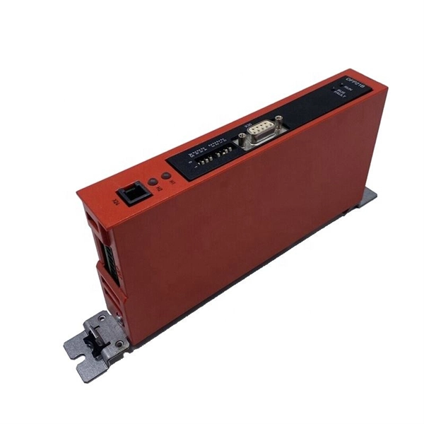
Distance relays, also known as impedance relay, differ in principle from other forms of protection in that their performance is not governed by the magnitude of the current or voltage in the protected circuit but rather on the ratio of these two quantities.OverviewIn, a protective relay is a device designed to trip a when a is detected. The. Electromechanical protective relays operate by either, or. Unlike switching type electromechanical with fixed and usually ill-defined operating voltage thresholds. Electromechanical relays can be classified into several different types as follows: "Armature"-type relays have a pivoted lever supported on a hinge or knife-edge pivot, which carries a moving contact. These relays may.
[PDF]
Hot aisle containment delivers significant operational and efficiency benefits compared to traditional or cold aisle approaches. HACS increases cooling capacity by 25-35%, enabling higher rack densities without additional cooling infrastructure. When implemented correctly, they improve efficiency, reduce energy consumption, extend equipment life, and enhance overall reliability. In this guide, we'll break down how hot aisle and cold aisle configurations. A data center aisle is the space between rows of server racks. Data center aisle containment uses physical barriers to keep hot exhaust air and cold supply air from mixing between rows of server racks. In a typical data center, racks are arranged in alternating hot and cold aisles. Cold air is. While liquid cooling is critical for managing extreme rack densities, hot aisle containment (HAC) systems capture and isolate hot exhaust air, and cold aisle containment (CAC) systems enclose and direct cold supply air. These approaches not only enhance cooling efficiency but also support. Cold aisle and hot aisle containment systems have emerged as essential strategies in modern data center airflow management. While these concepts are not new, their successful implementation requires detailed planning, precise engineering, and thorough analysis to deliver maximum efficiency. The right choice can dramatically reduce operating costs while.
[PDF]
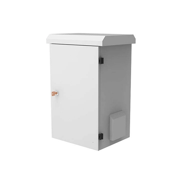
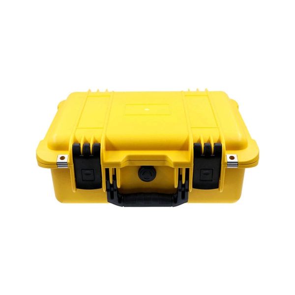
Empower your off‑grid projects and grid‑support applications with a reliable outdoor battery storage cabinet from TOPBAND. Engineered for harsh climates and demanding workloads, our outdoor battery storage cabinet delivers scalable LiFePO₄ energy storage in a rugged IP54‑rated. Lithium-ion batteries are the driving force behind today's portable power revolution—powering everything from electric vehicles to industrial equipment, tools, and communication systems. As their use expands across sectors, so do the risks associated with improper handling, charging, and storage. Whether. CellBlock Battery Storage Cabinets are a superior solution for the safe storage of lithium-ion batteries and devices containing them. Our practical, durable cabinets are manufactured from aluminum, and lined with CellBlock's Fire Containment Panels. CellBlockEX provides both insulation and. The Rack Battery Cabinet by PKNERGY is a versatile backup power solution tailored to meet specific energy needs. Customers can choose the required number of rack LiFePO4 batteries, and PKNERGY will configure the cabinet and PCS (Power Conversion System) into a fully functional energy storage. There are very few technology trends that have become so firmly established in recent years than the development of ever more powerful energy storage systems based on lithium (Li). For about 30 years, lithium-ion batteries and accumulators have been conquering the market for energy storage.
[PDF]
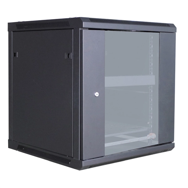
The global server rack market is witnessing significant demand due to rising data traffic and growing IT infrastructure, especially in hyperscale data centers. The server rack market is experiencing significant growth, driven by the escalating demand for data processing capabilities, the expansion of cloud computing services, and the emergence of edge computing 4 5 6. The global market for Data Center Rack Servers was valued at US$96. 1 million new data servers were installed globally, requiring optimized rack configurations to support power, cooling, and. Starting at USD 3. 67 Billion in 2026, the global Server Rack Market is set to witness notable growth. By 2035, it is projected to reach USD 7. 7% throughout the forecast period from 2026 to 2035. I need the full data tables, segment. Server Rack by Application (Finance, Securities, Data center, Others), by Types (Wall-mounted, Detached), by North America (United States, Canada, Mexico), by South America (Brazil, Argentina, Rest of South America), by Europe (United Kingdom, Germany, France, Italy, Spain, Russia, Benelux. The global data center rack market size was valued at USD 6. 26 billion in 2026 to USD 14. 55 billion by 2034, exhibiting a CAGR of 9. North. The global data center server rack market size accounted for USD 107.
[PDF]
If your high beams are not working, the most likely cause is a blown fuse or a burned-out bulb — both of which you can check yourself in under 15 minutes. That said, there are seven possible culprits, ranging from simple fixes you can handle at home to electrical faults that need a mechanic's. To be clear, I am not saying the highbeams are turning on and off, I mean the actual intellibeam system as indicated by the headlight symbol with the "A" in it on the DIC. When the system is on, the highbeams most of the time will work 100% as expected activating and deactivating when appropriate. Automatic high beam (AHB) systems, sometimes marketed under proprietary names like IntelliBeam or SmartBeam, are designed to enhance nighttime visibility by automatically switching between high and low beams. These systems use forward-facing cameras or sensors to detect light sources from oncoming. Affiliate programs and affiliations include, but are not limited to, the eBay Partner Network. 2021+ Ford F150 Discussion of the 14th generation F150. LED headlight High Beam Failure noticed that high beam on the drivers side LED headlight stopped working. Hooked up the reader and found fault code. Auto High Beam is a safety feature that controls the headlight operation and lights up the road in front using low and high beams. There is too much lag time for enabling the high beams. I just use the old skool manual headlights mode and switch my high beams as.
[PDF]
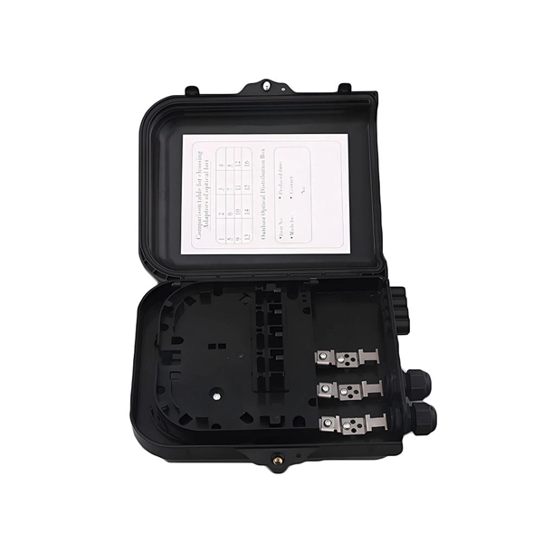
In modern FTTH architectures, the ODN is the physical fiber layer that distributes optical signals from the central office to end users. Operators consider ODN design as one of the most important factors affecting: Network coverage Optical loss performance Deployment cost. This passive layer is known as the Optical Distribution Network (ODN). Its role is to provide an optical transmission channel between the OLT and the ONU. The ODN network design is a physical facility that connects the communication room and user equipment, and is a key component. Short summary: The Optical Distribution Network (ODN) is the passive infrastructure linking the central office to the subscriber in FTTH. This guide delves into essential ODN components like splitters, distribution boxes, and ODFs, showcasing how Hainan ZTO Cable Co. It's the silent, robust highway that delivers blazing-fast Fiber-to-the-Home (FTTH) and 5G services. The maximum permissible optical power attenuation between OLT optical ports to ONT input is 28dB, which is by utilizing the so-called Class B optical network. At the heart of every Fiber-to-the-Home (FTTH) deployment lies the Optical Distribution Network (ODN) — a meticulously engineered passive infrastructure that enables operators to deliver massive bandwidth, low latency, and reliable service to millions of users. The ODN connects the Optical Line.
[PDF]