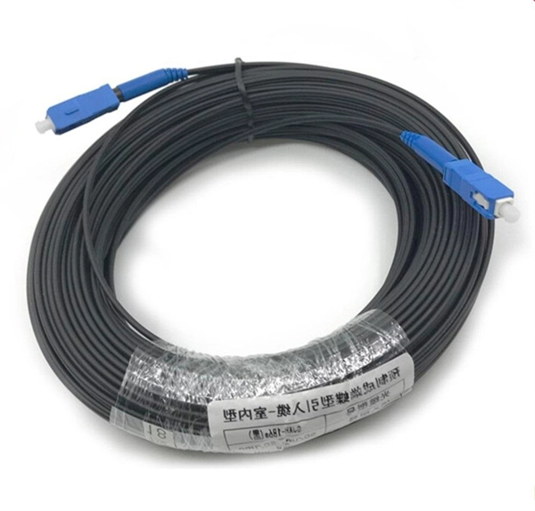
The OPM 510 and 520 are available in standard and high-power versions for the Telco and MSO markets. The OPM510 and OPM520 supports wavelengths of 850, 980, 1270 1300, 1310, 1490, 1550, 1577, 1623 and 1650nm. The rugged enclosure provides confidence when testing singlemode and. Count on Tempo Communications Optical Power Meters (OPM510/520) to test and maintain your fiber optic networks. Our optical power meters feature built-in calibration factors. Optical power meters and detectors have been served by Newport for over 30 years. The offering ranges from a low cost, hand-held meter to the most advanced dual channel benchtop power meter available in the market. Our 1936-R/2936-R series boasts state-of-the-art analog boards with a whopping 250. © Copyright© Santec Holdings Corporation. Demo the full range, from multi-use to dedicated PON and FTTH. VIAVI offers fast, cost-effective, and easy-to-use power meters for installation and maintenance of single mode and multimode fiber optic networks and. AFL is a trusted supplier of optical testing equipment with more than 30 years of experience and tens of thousands of units in use in the field. AFL's full range of power meters are used for testing single-mode and/or multimode fiber networks. Power meters with wave ID can detect two or more.
[PDF]
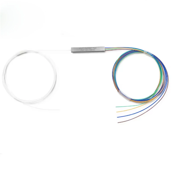
For TDM-PON, a passive optical splitter is used in the optical distribution network. In the upstream direction, each ONU (optical network units) or ONT (optical network terminal) burst transmits for an assigned time-slot (multiplexed in the time domain). In this way, the OLT is receiving signals from only one ONU or ONT at any point in time. In the downstream direction, the OLT (usually) continuously transmits (or may burst transmit). ONUs or ONTs see their own data through the address labels embe.
[PDF]
It is not recommended to place your router inside a cabinet as it can lead to poor Wi-Fi signal strength and potential overheating issues. Cabinets typically have materials that can interfere with the Wi-Fi signal, resulting in reduced coverage and slower internet speeds. For optimal performance. 💧 Water absorbs WiFi signal. Large aquariums or other significant water sources near your router can cause real connectivity issues, since water molecules are particularly effective at absorbing radio wave energy. 🏠 Router placement is your single most controllable variable. Careful planning ensures your router stays cool and your internet connection remains. Whether you're using a single Wi-Fi router or a mesh network, positioning your hardware correctly can make a major difference in speed, reliability, and coverage. Hiding your router in a cabinet or tucking it behind your TV might look tidy, but it's probably weakening your signal. After years of. In our increasingly connected world, a strong Wi-Fi signal is essential for everything from remote work to streaming entertainment. Yet many homeowners unknowingly place items near their routers that can significantly weaken their internet connection. Understanding what objects interfere with your. Positioning your router behind large furniture, under shelving units, or enclosed within cabinets can substantially degrade its performance.
[PDF]
The V-Sol V1600G0-B 4 Port GPON Optical Line Terminal (OLT) delivers reliable, high-performance broadband connectivity in a compact pizza-box design. Ideal for FTTx, FTTH, and FTTM deployments, it is suitable for remote areas, industrial parks, commercial buildings, and municipal. Continuing to browse this site indicates your agreement to use these cookies. Learn More Tenda Optical line terminals, also called optical line terminations (OLTs), serve as endpoints for passive optical networks (PONs). Engineered by Huawei, this device is ideal for FTTH, FTTB, and FTTX applications, ensuring fast, reliable, and scalable network connectivity. Perfect for deployments in sparse, remote, or cost-sensitive areas, as well as smart industrial parks. The best price and guaranteed service and backup from official computer suppliers in South Africa for the UB-UF-OLT-4 Ubiquiti U Fiber - 4 Port OLT Optical Line Terminal. Available from this online computer store delivering door-to-door in Johannesburg, Cape Town, Port Elizabeth, Pretoria. The V-Sol V1600G0-B 4 Port GPON Optical Line Terminal (OLT) is a compact, high-efficiency pizza-box style solution designed to meet the demands of flexible and fast FTTx broadband access. A small-scale GPON OLT for South African ISPs, community fibre networks, and.
[PDF]

The first thing you should do is locate the fiber optic cable that comes from the service provider. Once inserted, make sure it is. However, setting up a fiber optic connection to your router can seem daunting if you're unfamiliar with the process. This comprehensive guide combines industry standards with field-tested practices to ensure you achieve a rock-solid. Setting up a fiber internet connection requires understanding key hardware components and following a specific connection sequence to establish your home network. This guide details the necessary physical and digital steps to connect your fiber line and activate your internet service. The technician powers, tests, and activates the connection to confirm full speed and signal quality. * In some instances, the ONT and the router are all in the same device, generally called a combo unit. Here's a step-by-step guide to help you through it. Understand the Basics Before diving in, familiarize yourself with the components involved:. Tecnobits - Router - How to connect a fiber optic cable to the router Hello, Tecnobits! 👋 Connecting fiber optic cables to the router so that your internet flies like a spaceship! 😉 Explore with us on our website! And don't miss our latest news. See you soon! 🚀 How to connect a fiber optic.
[PDF]
At Multilink, we offer traffic power solutions to keep traffic signals, camera equipment, illuminated street signs and other tech up and running. Power traffic signals, camera equipment, lighting and other t.
[PDF]

Too many connections can cause too much signal loss. Clean your connections. As we discussed above, remove dirt, dust and oil from fingerprints with pen-style cleaners or alcohol wipes. Identify cable damage using a VFL tester. If identified, re-splice the cable. When issues like signal loss, slow speeds, or intermittent connectivity arise, systematic troubleshooting is key. This guide will walk you through diagnosing and resolving common fiber network issues efficiently. Why Do Fiber Networks Fail? Despite their robustness, fiber networks can fail due to:. Problems with fiber optic internet can range from signal attenuation to optic signal loss to equipment malfunctions. By shedding light on these common fiber internet problems and offering insights into preventative measures and advanced troubleshooting steps, we aim to empower network. Fiber optic troubleshooting is an essential skill for network administrators, technicians, and engineers responsible for maintaining and repairing fiber optic systems. These high-speed, high-capacity communication networks are increasingly replacing copper cables, offering superior performance and. Clean Fiber Optic connectors often to stop dirt and dust. Finding problems early saves money. It also stops long network downtime. Use the right tools to test for weak spots. These networks are the backbone of modern data transmission, offering incredible speeds and bandwidth.
[PDF]

This manual describes the protection, automation, control, and monitoring functions of the SIPROTEC 5 devices. In order to protect technical infrastructures, systems, machines and networks against cyber threats, it is necessary to implement – and continuously maintain – a holistic, state-of-the-art. Busbar Differential Protection Definition: Busbar differential protection is a scheme that quickly isolates faults by comparing currents entering and leaving the busbar using Kirchoff's current law. Current Differential Protection: This protection method connects CT secondaries in parallel and. A busbar protection is a protection to protect busbars at short-circuits and earth-faults. In the “childhood” of electricity no separate protection was used for the busbars. With increasing short-circuit power in the network. SIPROTEC 7SS60 7SS60 is a numerical differential current protection for busbars. It is suitable for all voltage levels and can be adapted to a large variety of busbar configurations. Busbar protection is critical for the safe and reliable operation of a power system. Related Article: Busbar Protection Like any other faults. Bus bar protection scheme shall be provided for 220KV system where the sub-station layout arrangement is with 3-bus system (Main 1, Main 2 & Transfer Bus) or two bus system with Main bus with bus section breaker & Transfer bus.
[PDF]
Find all you need for professionally buying optical fiber communication systems and devices: a comprehensive expert-curated directory of suppliers, scientific and technical background information, and an interactive AI-based tool with guidance for a structured decision process. T he MACOM PRISM-50D™MATP-05026D device is a 50G PAM4/NRZ PHY with integrated DSP and multiplexing functionality designed to enable single-wavelength 50G optical transceiver solutions. MACOM PRISM-50D™ is a highly integrated device offering low latency, low power, and a small foot print package. FIBERSTAMP 100G QSFP28 CLR4 optical transceiver are used for medium and long distance interconnection in data centers, complying with 100G CLR4 MSA specification and compatible with both 100G Ethernet and InfiniBand EDR transmission protocols. The product has a built-in pair of 4-channel CWDM MUX. GIGALIGHT 100G QSFP28 LR4 optical modules are used for long-distance transmission in the datacom or telecom field and are compliant with IEEE 802. 3ba 100GBASE-LR4 Ethernet transmission protocol, with optional dual-rate versions compatible with 100G Ethernet and OTN OTU4. The package contains a high-speed DFB laser chip, thermoelectric cooler, thermistor, optical isolator, and a rear-facet monitor. Contact Optilab for more information and pricing options. The Optilab DML-1550-PM-M is a directly modulated laser (DML) module with Polarization Maintaining fiber output at 1550 nm. You appear to be.
[PDF]
Mouser offers inventory, pricing, & datasheets for Transimpedance Amplifiers. Pricing (USD) Filter the results in the table by unit price based on your quantity. A tariff of 40% may be applied if shipping to the United States. A. Chopper / Zero-Drift Amplifier: Actively cancels offset and drift, enabling long-term DC accuracy in precision weigh scales and low-frequency seismic sensors. Shop DigiKey's large in-stock selection of Instrumentation, Op Amps, Buffer Amps. Transimpedance Amplifiers are available at Mouser Electronics. CITY:DOVER STATE:DE ZIP:19901 BUSINESS PHONE:310-490-2001 MAIL ADDRESS: STREET 1:26156 CORDILLERA DRIVE CITY:MISSION VIEJO STATE:CA ZIP:92691 <headerData> <submissionType>C/A</submissionType> <filerInfo> <filer> <filerCredentials> <filerCik>0002009137</filerCik> <filerCcc>XXXXXXXX</filerCcc>. Pricing (GBP) Filter the results in the table by unit price based on your quantity.
[PDF]
Comparison of GPON and XGSPON SFP Module Categories and Optical Factors Optical Link Loss Factors Analysis Example of Link Budget Calculation (GPON C+, 1:16 Splitting) Design Recommendations Commercial vs ISP Scenarios 1. Overview. Discover our selection of GPON, EPON, and XG (S)PON ONT/ONU devices. Choose from reliable Optical Network Terminals for seamless connectivity and efficient network solutions. The ONU (Optical Network Unit) price represents a crucial consideration in modern telecommunications infrastructure. This essential component serves as the endpoint device in fiber optic networks, converting optical signals into electrical signals for end-user consumption. 4G/5G WiFi, ideal for FTTH networks. The global Optical Network Unit(ONU) market is projected to grow from US$ million in 2024 to US$ million by 2031, at a CAGR of %(2025-2031), driven by critical product segments and diverse end‑use applications, while evolving U. tariff policies introduce trade‑cost volatility and supply‑chain. Deploying an ONU (Optical Network Unit) network can be a complex and costly endeavor. As an authority on the subject, let me guide you through the intricacies and expenses involved in setting up such a network. Overview The Optical Link Budget is a critical parameter for evaluating.
[PDF]
The MALD-37059 is a four channel CDR with a directly modulated laser (DML) driver for use as a transmit device in optical modules. EML: Separates the light generation function from the modulation function. It uses an external modulator to shape the signal, which improves performance in high-speed, long-distance transmission. On paper, the difference looks small. In real deployments, it can completely change the behavior of a. DML refers to a directly modulated laser. This laser is also called a distributed-feedback laser diode (DFB) since it uses a distributed feedback structure. There are two modulation techniques for optical modules, DML and EML, which are briefly introduced in this article. The optical signal transmitted in the optical fiber is not constant, but is modulated, intensity changes in the optical signal, the following is a description of the characteristics. Optical transceivers primarily adopt two mainstream modulation technologies: DML and EML. This article provides a brief introduction to both. Basic Principle of Optical Transceivers The core function of an optical transceiver is to achieve optical-electrical conversion. Ethernet layer: business as usual. 400GE or 4x100GE breakout Optical channel:.
[PDF]
For submarine applications, Raman amplification minimizes the number of underwater repeaters, enhancing reliability and cost-efficiency, while in terrestrial setups, it facilitates ultra-long-haul links over thousands of kms with reduced infrastructure needs.OverviewRaman amplification is a way of increasing the signal strength in an optical fiber. It is often used in a fiber that carries a signal for a long distance (such as in an undersea cable). Technically, it works by stimulating. • Poem, Eilon; Golenchenko, Artem; Davidson, Omri; Arenfrid, Or; Finkelstein, Ran; Firstenberg, Ofer (26 October 2020). • •.
[PDF]