Find the Latest Global Communication Tower tenders online with TendersOnTime. Advertisement for Request for Qualifications (RFQ) Department of General Services Real Estate Services Division Project Management and Development Branch RESD-PMDB 2024-16 CONSTRUCTION MANAGEMENT SERVICES COMMUNICATION TOWER PROGRAM VARIOUS LOCATIONS, STATEWIDE Construction Management Services as. Statewide program seeking a qualified firm to replace telecommunications infrastructure with new towers, radio vaults, and supporting infrastructure across California. Our platform offers unrestricted access to eProcurement notices, eTenders, Tender results, and corrigendum updates from 600,000+ government and private tender websites, eProcurement Portals and newspapers from around the. Department of General Services Real Estate Services Division Project Management and Development Branch The Department of General Services (DGS), Real Estate Services Division (RESD), Project Management and Development Branch (PMDB) is requesting Statements of Qualifications (SOQ) from Construction. Are you searching for the latest Communication Tower Tenders from trusted sources across the globe? Tender Impulse is the go-to tender website for businesses seeking verified and timely updates on public tenders, government tenders, and business tenders in a wide range of sectors. With our smart.
[PDF]
Communication towers are tall steel structures used to raise antennas to higher elevations in order to extend service coverage and improve wireless communication performance. Antennas are typically mounted at the highest practical point to increase service radius. Pile Foundation: In areas with loose or unstable soil, deep foundations known as piles are driven into the ground. These piles are often made of concrete or steel and are designed to reach a stable layer of soil or bedrock, ensuring the tower remains secure. Raft Foundation: For heavy towers or. Modern communication tower technology & infrastructure represents the essential physical backbone of our global wireless world. This specialized field combines civil, structural, and electrical engineering to create the tall structures that support antennas for mobile networks. The construction of these towers requires careful planning, precise engineering, and skilled labor. In this section, we will delve into the. There are four main types of telecommunication towers: lattice towers, monopole towers, guyed towers, and stealth towers. These towers play a crucial role in enabling wireless communication by providing a platform for the installation of radio equipment and antennas. A typical communication tower.
[PDF]
This article reveals the list of the best 10 communication tower manufacturers in the world, who are the bankrollers of the telecom revolution. Telecom Tower Companies play a crucial role in enabling global communication by providing the infrastructure necessary for wireless and broadband connectivity. These companies specialize in designing, building, and maintaining towers that support various network services, from 4G and 5G to. From traditional lattice and guyed towers to advanced self-supporting and monopole designs, these companies play a vital role in ensuring network reliability and high-speed data transmission. XY Tower is a Chinese-based leading. Our AI-powered database combines millions of company and investor profiles, making it simple to filter, search, and benchmark opportunities. Explore this list as a starting point and connect with us to see how Inven can help you build tailored lists for sourcing and market discovery. From wireless carriers to WISPs to companies backhauling data over microwave, people need tower space. When an organization needs to expand their network, it leases space from another company. In fact, many modern companies an. Total does not include foreign-owned tower portfolios. In some cases the tower company might not own the structure, but has lease rights and the ability to acquire the towers after a set period of time. Totals do not include DAS and small cells. The Top 100 Tower Companies in the U.
[PDF]
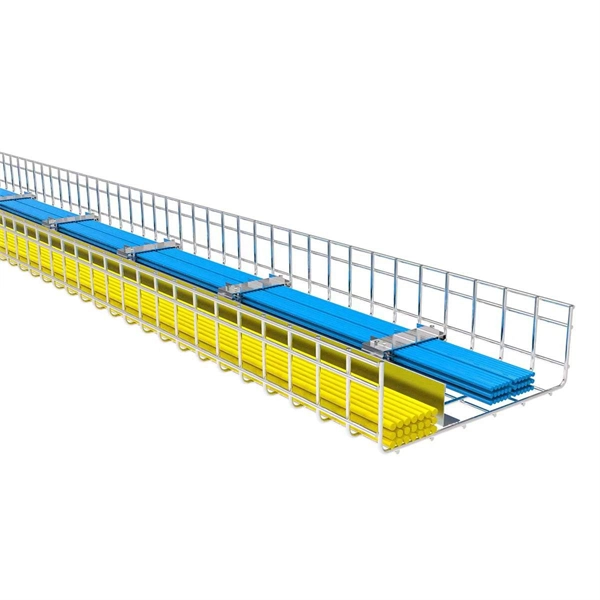
Free download of the complete cell tower site in DWG or CAD block format. Site layout; tower construction; equipment foundation details;. Communication towers are essential infrastructure for modern society, enabling the transmission of voice, data, and video signals across vast distances. The construction of these towers requires careful planning, precise engineering, and skilled labor. In this section, we will delve into the. During construction, the following considerations can reduce the risk of take of birds: Schedule all vegetation removal and maintenance (e., general landscaping activities, trimming, grubbing) activities outside of the peak bird breeding season to reduce the risk of bird take. Breeding seasons. Comprehensive Guide to Civil Construction for Telecom Tower Sites In the ever-evolving landscape of telecommunications, the construction of tower sites serves as the backbone for reliable network connectivity. Telecommunication towers are essential. PURPOSE: This policy provides clarification of the requirements for DSA approval of plans and certification of construction for state-owned, state-leased or privately owned towers and poles utilized for essential services communication and for essential antenna and equipment mounted on the towers.
[PDF]
They offer a variety of options to suit your needs and budget, with two particularly attractive packages: the Start Offer and the Premium Offer. Here's a breakdown of both, along with a handy comparison table to help you decide which one is right for you. The NF-8505 is a network cable tracer and optical wire tracer that identifies and tests both copper. Htb-gs-03-a/b 1000m single-mode fiber optic ethernet media converter brand generic connector type. Watch on smart TVs, PlayStation, Xbox, Chromecast, Apple TV, Blu-ray players and more. The initial attached cost is 350,000UGX for the starter pack which comes with a broadband SIM card, free 51GB for 30 Days, high quality installation, maintenance for 3 years and an Airtel-owned Outdoor Unit (ODU) with an Indoor Unit (IDU) – Customer's Premises Equipment. Installation @. Blue Crane Communications offers state-of-the-art fiber internet connectivity for homes and small businesses. Our fiber optic network delivers lightning-fast speeds with minimal latency, perfect for streaming, gaming, and working from home. Fast and reliable home internet services from Blue Crane. Experience lightning-fast internet with Simba Fiber, Uganda's leading fiber-optic internet service provider. Enjoy uninterrupted Internet. Roke Telkom The company has multiple products for its population. These include fixed wireless and fiber solutions in excess of 100 Mbps. Even so, Rokespot offers innovative Wi-Fi service that.
[PDF]

Get answers to frequently asked questions about broadband services at BTC Bahamas. At Lightcommunication Company, we specialize in comprehensive fiber optic solutions, ensuring superior connectivity through expert services in installation, splicing, and network maintenance. We strive to revolutionize communication by providing cutting-edge fiber optic services that empower. BTC, also known as the Bahamas Telecommunications Company, is the national telecommunications company of the Bahamas. It offers a range of internet services, including fibre optic and DSL connections, and has a wide network of fibre optic cables, allowing it to provide high-speed internet to both. Clear Fiber Technology Solutions is a leading and reputable Telecommunications Contracting and Consulting Firm serving the Bahamas and Caribbean area. We understand the importance of Professional and Reliable Communications Services. We take a comprehensive approach to secure solutions, providing. Our aim is to provide reliable, cost effective, comprehensive solutions with efficient service to assist you in building I. infrastructure you can depend on. We want to be your partner of choice. call on us when you need to build out, upgrade or expand. Along the way we make it our mission to enrich lives and businesses through reliable, fast and future ready technology. Cable Bahamas nurtures education, wellness and cultural growth through dedicated partnerships and.
[PDF]

Optical Fiber Communication (OFC) revolutionizes modern telecommunications, enabling rapid data transfer across long distances with minimal signal loss. This comprehensive review explores OFC's historical evolution, core principles, components, and versatile applications. It traces OFC's. Additionally, optical fiber is lightweight and less susceptible to noise (no electromagnetic induction). Optical fiber consists of a cylindrical core that propagates light and a concentric cladding that surrounds it. The cladding's refractive index is slightly smaller than that of the core, which. Fibre optics and optical communications is the use of thin strands of glass for sending information encoded into light over long distances. Total internal reflection prevents light inserted into one end of the fibre from escaping through the sides. Keywords: Optical fibers, communication systems, data. Figure 1: Illustration of the inverse-square law of light intensity – the light's intensity diminishes with the square of the distance, which free-space optical signals must overcome (leading to very weak reception at long range) Figure 1 illustrates how light intensity decreases as distance.
[PDF]

This practical file details experiments conducted in Optical Fiber Communication, covering modulation techniques, system components, and performance analysis. An optical fiber is a glass or plastic fiber designed to guide light along its length, widely used in fiber-optic communication, which permits transmission over longer distances and at higher data rates than other forms of communications. Fiber-optic communication is a method of transmitting. Availability of plastic optical fiber (POF) The plastic optical fiber used in some of these experiments is available for science distributors. It is a 1000micron (1mm) POF available from several suppliers. FOA has samples available at no cost for teachers at schools in the US. Key experiments include amplitude modulation, frequency modulation, and pulse width modulation, aimed at understanding fiber optic systems. This document summarizes 10 experiments on optical fiber communication: 1. Studying a 650mm fiber optic analog link and the relationship between input and received signals. Optical fiber communication Laboratory Optical fiber communication Laboratory List of Experiments: 1. To set up a analog optical fiber link 2. To measure the characteristics of LED and LASER 5. Tech curriculum designed to provide a comprehensive understanding of optical fiber communication systems. This lab offers an immersive, web-based simulator that enables you to explore and experiment with key concepts in optical.
[PDF]
Underground fiber optic cable carries the vast majority of the world's internet traffic, phone calls, and digital data. These cables are buried beneath streets, sidewalks, and rural land to connect homes, businesses, data centers, military installations, and city infrastructure. While the glass. Underground fiber optic cable is designed for direct burial or conduit installation and is widely used in FTTH networks, backbone infrastructure, and industrial communication systems. This guide explains underground fiber optic cable types, installation methods, burial depth, and practical. One of the key components driving this connectivity is underground fiber optic cable. It has been increasingly used in telecommunications networks around the world. Introduction of The Buried Fiber Optic Cable Fiber optic cables have revolutionized the way we transmit data, offering unparalleled speeds and reliability.
[PDF]
HOPPECKE has delivered over 2.5 million FNC® cells to customers in the railway sector around the world. This success is down to the many advantages that the FNC® technology has over other energ.
[PDF]
The key lies in their fully sealed design, acting as a “protective shield” for the cabinet, effectively preventing dust, salt spray, and high-temperature air from entering. So, how can this more reliable cooling solution become more economical to support large-scale 5G. ESTEL designs each Telecom Power System and outdoor telecom cabinet to adapt to these challenges. You get reliable performance through robust materials, smart energy management, and advanced engineering. ESTEL's dedication to quality, innovation, and international standards ensures your equipment. With 5G base stations, smart light poles, outdoor communication cabinets and other infrastructures spreading all over urban and rural areas, outdoor telecommunication equipments are facing severe tests such as extreme temperature difference, humidity and rain, and dust intrusion. Traditional. Available in different configurations, Delta OutD cabinets are designed to protect equipment from external threats in all climates from the tropics to the arctic. In addition to traditional cooling methods, Delta's new hybrid cooling options revolutionize the cost structure of thermal management. Featuring a robust steel structure with IP-rated protection, it ensures reliable operation against dust, rain, heat.
[PDF]

Optical return loss is the amount of light that is reflected back to the source, this reflected light is measured at each connector and splice at each point over the entire fiber link. This is always measured in dB (decibels) and will be displayed as a negative number. The closer the number is to. The polish of a singlemode fiber endface plays a significant role in reflectance. Understand what you need before you specify. The Institute of Electrical and Building the ORL story Electronics Engineers (IEEE) recently Within a fiber-optic channel or path-released new specifications within way. Optical Return Loss (ORL) in fiber optics refers to the amount of light that is reflected back toward the source in a fiber link. ORL is usually expressed in decibels (dB) as a positive value, with. Return loss (RL) is also called reflection loss. When high-speed signals enter or exit a part of an optical fiber, such as an optical fiber connector, discontinuity and impedance mismatch may cause reflection, which is the return loss of an optical fiber. Poor ORL is commonly caused by dirty connectors, poor splices, mismatched connector types, or damaged fibers. ORL is measured using ORL meters. Home Coherent Optics Optical Return Loss (ORL) Explained Comprehensive Guide to Understanding and Managing Back-Reflections in Fiber Optic Systems What is Optical Return Loss (ORL)? Optical Return Loss (ORL) is a critical parameter in fiber optic systems that quantifies the amount of light.
[PDF]
The data from September 2023 shows that 21 countries have achieved penetration rates higher than 50%. The UAE leads the ranking with 99,3%, while Singapore positions itself second at 97,1%. Hong Kong (95,3%), China (92,9%), and South Korea (91,5%) complete the top 5 positions. This report provides an analysis of Omdia's Fiber Development Index (FDI). The FDI quantifies and ranks the level of investment in fiber optical networks across nine metrics on a country-level basis. This analysis helps industry stakeholders, including policymakers, regulators, service providers. The Mobile Connectivity Index measures the performance of 173 countries against the key enablers of mobile internet adoption. In the European. Global Fiber-optic Cable key players include ZTT, YOFC, Prysmian, HTGD and FiberHome. Global top five manufacturers hold a share about 40%. Asia-Pacific is the largest market, with a share over 60%, followed by North America, with a share about 16 percent. 8 billion by 2029 from USD 3. 4% from 2024 to 2029. Rapid expansion of data centers, cloud services, and 5G infrastructure is driving strong adoption of fiber optic solutions. 80% during the forecast period (2023-2032). This expansion is driven by surging demand for high-bandwidth networks, 5G.
[PDF]
1. Scope: This quality procedure is made to enumerate to perform the fiber optic cable installation, termination and testing work in SAOMPP Project. 2. Purpose: The purpose of this quality procedure is to establi.
[PDF]

In this video im showing and explaining how to climb a power pole using a fall protection belt, also drilling into a pole and framing it for 1/4 strand that will supports the fiber optic cable. more. Deploying fiber above ground on poles or towers removes the need for underground digging and is particularly useful when the ground is uneven, rocky or both. Aerial installation is generally much less costly than underground construction also. Fiber in a duct solutions have a major aesthetic. The Fiber Optic Association, Inc. (FOA) was founded in 1995 to help develop the workforce to build the fiber optic networks to support a rapid expansion in communications and the Internet. This lesson covers the installation of poles and. ADSS (All Dielectric Self Supported fibre optic cables) OPGW (Optical Ground Wire) The installation methods for fibre optic cables are largely the same as those with conventional copper cables. These may be considerably different from those of the copper cable. When installed correctly, ADSS cables can last more than 25 years, providing stable, high-speed communication even in difficult outdoor environments. But to get the best.
[PDF]