A fiber router includes an actual port for this connection, so you won't need an adapter that translates Ethernet into fiber optic signals or vice versa. It should be a truly plug-and-play experience, so long as you have a fiber optic modem and the accompanying service plan. Fiber internet transmits data using light signals through fiber-optic cables, which differs from traditional DSL or cable internet. Instead of a modem, fiber connections require an Optical Network Terminal (ONT), a device that converts fiber signals into an Ethernet connection. Most fiber ISPs. Which either needs a fiber optic port, or an SFP port, plus a fiber otpic-to-sfp tranceiver. Given that, how come 95% of the 5G, 1Gb/s routers I see in stores still only have ethernet ports? Rather than moving to fiber or SFP ports, consumer industry decided to go with NBASET running 2. Here's what you need to know: A fiber router, or fiber optic router, is a router that is specifically equipped. Fiber vs. Cable Internet: Here's a modem connected to a service line and a Wi-Fi router's WAN port. A cable modem generally includes a service port (for the coax line) and one or more RJ45 network ports to connect to a router. 1 with its multi-Gigabit capability is the. The good news is that once you're set up with an ONT, you're good to go for the future—you can simply plug any wireless router you like into its Ethernet port to set up a wireless fiber home network.
[PDF]
Step 3 Remove the cables or optical modules from the old card. Press the two green locking clips in the middle of the card to eject the ejector levers. Turn the ejector levers outward and slowly pull the card out. Place the replaced. Unplug the optical fibers from the optical module before removing it. Install or remove optical fibers carefully to avoid damaging the fiber connectors. If an optical module cannot be completely inserted into an optical. Page 7 Optical port USB storage device Wi-Fi terminal 1. Wear an ESD wrist strap or ESD gloves when replacing the optical module. Therefore, replace an optical module only when you confirm.
[PDF]
F port is FastEthernet interface and fast Ethernet port, also known as 100M port. It is mainly used to connect switches or computers. When selecting or configuring a network switch, you often encounter ports labeled G, F, E, and S. Understanding the differences between these port types is essential for proper network design, cable selection, and optical module compatibility. Below, we break down each port type in detail. You can use commands to set bandwidth. This article will focus on the four common interfaces: G port, F port, E port, and S port to facilitate understanding before installation. S port The meaning of Serial interface is also called high-speed. S port is fully called serial interface, also known as high-speed asynchronous serial port. E port It is the Ethernet interface. Each Fibre Channel port can be used as a downlink (c onnected to a server) or as an uplink (connected to the data center SAN network).
[PDF]

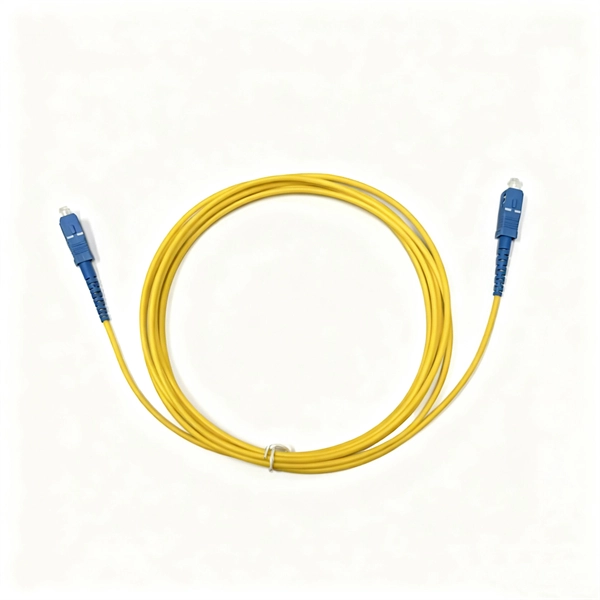
The first thing you should do is locate the fiber optic cable that comes from the service provider. Once inserted, make sure it is securely. However, setting up a fiber optic connection to your router can seem daunting if you're unfamiliar with the process. Why Use Fiber Optic Internet? Before diving into the setup, let's quickly. Ensure your fiber optic router has an available WAN (Wide Area Network) or Ethernet port for the fiber optic modem. It's thin, flexible, and usually comes with connectors on both ends. Power Cables: Get power cables for both the. The fiber optic cable does not plug directly into a standard home router because the signal type must be translated. The fiber line terminates at the Optical Network Terminal (ONT), which is typically supplied and installed by the internet service provider. This specialized equipment serves as the. The process to connect fiber optic cable to router requires careful attention to detail, but I'll walk you through every critical step with the precision and clarity you deserve. Here's a step-by-step guide to help you through it. Understand the Basics Before diving in, familiarize yourself with the components involved:. Follow along as we take you through the step-by-step process of installing fiber internet! From preparing the site to connecting the final cables, we'll show you what goes into bringing high-speed internet to your doorstep. Whether you're a tech enthusiast or just curious about how it all w.
[PDF]
Locate your ONT/ONU: This is typically a small box provided by your ISP, often located near where the fiber optic cable enters your home. Connect the fiber optic cable: Plug the fiber optic cable from your ISP into the designated port on your ONT/ONU. This is usually clearly labeled. However, setting up a fiber optic connection to your router can seem daunting if you're unfamiliar with the process. In this guide, we'll walk you through how to connect a fiber optic cable to a router safely and efficiently. Why Use Fiber Optic Internet? Before diving into the setup, let's quickly. To set up your router for fiber internet quickly, connect the router to your fiber modem, access the router's settings via a web browser, and input the provided ISP credentials. Make sure to update the firmware, configure Wi-Fi security, and customize your network name for optimal performance. With. Setting up a fiber internet connection requires understanding key hardware components and following a specific connection sequence to establish your home network. Here's a simple guide to help you through the process: 1. Check Your Fiber Optic Equipment Before you start, make sure you have the necessary equipment: Fiber Optic Modem (ONT – Optical Network Terminal):.
[PDF]
Unmanaged provides plug-and-play simplicity Auto-speed negotiation Selects individual port speed automatically, depending on client capabilities; removing the need for manual intervention enables simple.
[PDF]

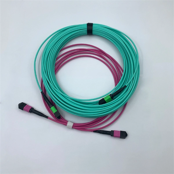
Use two fibers: one dedicated to TX, the other to RX. Both sides transmit and receive at the same wavelength (common values: 850 nm MM, 1310 nm/1550 nm SM). The front panel is usually labeled TX and RX, and you cross-connect TX→RX, RX→TX with a duplex patch cord. Switch optical port intercommunication means that the optical fiber ports of two switches are connected to each other to achieve the purpose of network connection. The connection between two or more Ethernet switches in a certain way (Uplink port, etc. ) is called the cascade. SFP modules insert into these slots and and require two strands of fiber, typically duplex Using multi mode fiber (for runs under 1000 feet) or duplex single mode fiber (for runs over 1000 feet). This is a cost-effective and high performance way to connect network switches. Use one fiber strand for both. The switch supports 10 Mbps, 100 Mbps, and 1000 Mbps connections. Using Gigabit Ethernet (1000 Mbps), the switch sends files across the network at speeds up of to 2000 Mbps due to the full-duplex nature of Gigabit Ethernet connections. You can either connect 24 Ethernet copper cables or 22 copper. Port types are limited to two: optical and Ethernet. Optical ports on switches typically accommodate optical modules for transmitting data via fiber optic cables. In situations where there's a shortage of Ethernet ports, some users may insert Ethernet port modules into optical ports to connect with.
[PDF]
Switches come in three types: those with purely Ethernet ports, those with purely optical ports, and those with a combination of both. Port types are limited to two: optical and Ethernet. Optical ports on switches typically accommodate optical modules for. The optical ports on the switch are usually paired together, with one TX sender and one RX receiver. The. Optical switching represents a fundamental technological evolution, shifting data routing from the domain of electrons to the realm of photons, or light. This transition allows data to remain in its native optical form as it travels through fiber optic networks, eliminating the need for. An all-optical Ethernet switch is a network switch whose service ports are entirely optical, meaning every interface uses fiber rather than copper. This design enables end-to-end optical signal transmission, avoiding the conversion between electrical and optical signals at the switch port level. Copper ports, also known as RJ45 ports, are the most common type of Ethernet switch ports. These ports use twisted-pair copper cables (Cat5e, Cat6, Cat6a, etc. Copper ports are widely used in local area networks (LANs) due to their cost-effectiveness and ease of installation. They can function as core, aggregation, and access devices on campus networks and connect to upstream and downstream devices.
[PDF]

Are SFP modules universal? No — and using the wrong one can lead to errors or no connection at all. But with the right information and a trusted supplier, you can avoid compatibility issues and save money. Q1: Can I use a third-party SFP module in my Cisco switch?. SFP (Small Form-factor Pluggable) is a compact, hot-pluggable network interface module used to connect network devices (switches, routers, firewalls) to fiber optic or copper cables. It helps your device connect to a fibre optic or copper cable — like a SIM card for your phone, but for your network. SFPs are used for different network types and speeds. Switch optical modules, which convert electrical signals to optical signals and vice – versa, and optical interfaces, which serve as the physical connection points, play a pivotal role in determining the speed, distance, and reliability of data transmission. Transceiver compatibility is a key concern in enterprise network deployments. Can an SFP. Every network engineer runs into it: the optical transceiver that should work, but doesn't. First, there's form factor—the SFP you used last year won't fit the QSFP-DD ports your new switches need. Then protocols and speeds complicate things. An optic that handles Ethernet might fail entirely on a.
[PDF]
The ONT connects directly to the fiber-optic line from your internet service provider, converting light signals into a usable internet connection. From there, the router takes over, distributing that connection to create your local area network (LAN) and manage traffic between all your devices. In contrast to the modem situation, any router can work with a fiber connection. That's no exaggeration, either—if it has an Ethernet port (and nearly every modern router does), you can connect it to your ONT and you'll have a Wi-Fi network. Fiber providers generally provide a router to customers. The ONT converts fiber network signals from light into copper and electric (Ethernet wiring) for your router to use. The ONT communicates with your provider's fiber network at the Termination Point, or TP, installed by your provider using an optical fiber cable. It's a key part of any Fiber to the Home (FTTH) setup. If your home uses cable Internet instead of fiber, you don't need an ONT. You'll use. Think of the ONT as a translator. Fiber internet works by sending data as beams of light through tiny glass strands (yes, really!). But your home devices — like your laptop, smartphone and smart TV — can't interpret light signals. That's where the ONT comes in. It converts those light signals into. This is the only live wire, that goes to the bedroom on the 3rd floor where the FiOS modem router lives. Yes, we have a (non-operational) satellite dish. In the first pic, the.
[PDF]
Enable or disable the PoE function on S series switches: 1. system-view. Huawei's comprehensive portfolio of products and solutions enables you to realize smooth digital transformation and rapid growth of virtualization, Big Data, and cloud services. Huawei switches already help customers achieve success in industries such as finance, Internet, retail, education. Welcome to our user-contributed teardowns on the hottest new gadgets. You can write your own teardown, check out how others are contributing with their teardowns, and even check out disassembly photos and comprehensive hardware analysis. Why should I create a teardown? The Lenovo M910s has been. One of them in particular involves the use of Power-over-Ethernet (PoE), but as I don't already have any “standards-complaint” PoE equipment, I needed a cost-effective means of getting a workable set-up. In the early days of 100BASE-TX Ethernet, only two of four pairs of the Ethernet cable were. If one or multiple PoE chips of a PSE are suspended, the port connected to a PD cannot detect the suspension and fails to power the PD. In this case, you can reset the PoE chip. The PoE chip is reset. If PoE power modules are working normally, check whether the PoE card and DIMM are working normally. If the register. Only electrical interfaces of switch models with PWR or PWH in the device names support the PoE function. All views Before using the PoE function, run the display poe device command to check.
[PDF]
This diagram shows how the RJ45 cable is connected to the PoE switch, allowing it to power devices such as IP phones and cameras. In this article, we will explore the wiring diagram for a PoE switch, which provides a visual representation of how the switch connects to various devices. Each device is represented by a. Do you want to set up a new computer network in your home or office? Chances are, you'll need a Poe switch wiring diagram. Not only do these diagrams provide all the information you need to install a network, but they also help make the process easier and more efficient. For those who don't know. A PoE Switch, also known as Power over Ethernet Switch, is a network device that allows users to power and connect devices such as IP cameras, VoIP phones, and wireless access points. In essence, a PoE Switch can be described as regular switch with added ability of Power over Ethernet which allows. PoE technology enables the transmission of both data and power over a single ethernet cable, simplifying network setups and eliminating the need for additional power sources. This is particularly useful in scenarios where devices like IP cameras, wireless access points, or VoIP phones need to be. Here, you can see the details, Keep the copper strips towards your face and count the pin number or pin position from left to right. The T568B also has a total of eight pins and sight different colors.
[PDF]
PoE switches (Type 1) comply with the IEEE 802. 3af standard, which specifies the maximum power delivered over Ethernet cables. 4 watts of power per port, while PDs can consume up to 12. UPoE supports higher-powered devices, including advanced Wi-Fi 6 APs, video conferencing endpoints, large-screen digital signage, and compact desktop switches. The latest IEEE standard (802. 3bt), supporting up to 90 W per port. UPoE+ can power advanced devices like LED lighting systems. Power over Ethernet (PoE) is a widely used LAN technology that provides DC power to endpoints over existing copper Ethernet cabling used for data connectivity. This eliminates the need for separate power supplies for devices such as IP cameras, VoIP phones, or wireless access points.
[PDF]
Follow these steps to connect your WiFi router or modem using the TP-Link TL-POE10R POE Splitter: Plug one end of a Cat6 Ethernet cable into a POE port on the POE switch. This cable will carry both data and power. Connect the other end to the Ethernet input port of the TP-Link POE. We can use TL-POE150S and TL-POE10R to expand the network for the place where power line can not reach or there is no outlet. In the topology shown as above, both TL-POE10R and the device which connect to it do not need external power adapter, the TL-POE150S can provide power supply and data for. In this video, we dive into how to use the TP-Link TL-POE10R POE Splitter to supply power and LAN connectivity to a WiFi router, modem, or access point from a CCTV system POE switch. This powerful device simplifies your network setup by delivering both power and data through a single Ethernet. Connecting TP-Link cameras to a POE switch is a seamless, plug-and-play process that powers and networks your security system in minutes. Simply link the camera to the POE switch using a single Ethernet cable—handling both data and power—then configure via the TP-Link app for live viewing and. The Injector sends power and data over the Ethernet cable to the Splitter. Then the Splitter separates the data and power back into two cables and delivers them to the remotely located access point or other network device that requires a 5/9/12-volt power input. 2 Features Complies with IEEE.
[PDF]

On this page you will learn what differentiates a PoE enabled switch from a regular LAN switch, when you should use a PoE switch versus a PoE injector and, what exactly is PoE (Power over Ethernet) technology. A PoE switch simplifies network installation by providing power and data transmission over a single Ethernet cable. However, to take full advantage of a PoE switch, it's crucial to understand how to use it properly. In this blog, we will guide you through the key steps to ensure a successful PoE. A PoE (Power over Ethernet) switch is a network switch that delivers both power and data through a single Ethernet cable to connected devices such as IP cameras, VoIP phones, wireless access points, and IoT devices. PoE Switches - what are they, when to use them, what to know about them, and when not to. Written by Don Schultz, trueCABLE Senior Technical Advisor, Fluke Networks Copper/Fiber CCTT, BICSI INST1, INSTC, INSTF Certified You just bought a nice PoE (Power over Ethernet) switch with cameras and access points. You realize you need to buy Ethernet cable to handle this, but you are a bit. Power over Ethernet (PoE) is a widely used LAN technology that provides DC power to endpoints over existing copper Ethernet cabling used for data connectivity. This allows a single cable to provide both a data connection and enough electricity to power networked devices such as wireless access points.
[PDF]