Even when a network is designed correctly, real-world conditions—fiber handling, connector cleanliness, splices, environmental stress, and aging—can gradually increase attenuation or introduce reflections and interference. Fiber optic patch cords are often treated as low-risk consumables, yet a large percentage of optical link failures originate at the patch cord level. Unlike backbone cables, patch cords are frequently connected, disconnected, bent, and handled by technicians, making them the most vulnerable. Optical attenuation is the gradual loss of flux (light intensity) as an optical signal travels through a fiber. Measured in decibels (dB), it's the logarithmic ratio of the output power to the input power. Every network has a "loss budget". Field guide for diagnosing high fiber optic attenuation. Learn to use the OTDR to identify contamination, micro-bends, and poor splices, ensuring your 400G network links remain within budget. This article explains practical, engineering-focused ways to mitigate signal. This measurement helps determine the efficiency of a fiber optic system. Several factors contribute to signal attenuation. These include absorption, scattering, and bending losses. Each factor plays a significant role in the overall performance of a network. Whether you're a network engineer, IT manager, or service provider, understanding these challenges and how to address them is critical for maintaining high-performance, reliable.
[PDF]

In this post, we'll walk you through practical tips, essential tools, common pitfalls, and the techniques that will help you get your fibre patch cable installations right the first time. Correct patch-cord installation is essential for maintaining low insertion loss, stable return loss, and long-term reliability in both indoor and outdoor fiber networks. Proper handling, routing, cleaning, bend-radius management, and connector alignment ensure that the optical link meets design. Proper connection of fiber optic cables is essential to harness these benefits fully, as even minor errors can lead to significant performance issues like signal loss. This guide addresses expert-certified best practices applied by professionals in the telecommunications, data. Yingda outlines the tools and materials needed to install fiber optic patch cords, as well as a complete step-by-step installation guide and important safety considerations to take. We will also tie this procedure back to the earlier discussion of multi-mode fiber types (OM1 to OM5) and connection. The Flex-Angle boot is designed to bend any angle or direction from straight to 90°. OMC flex angle boots for LC&SC fiber optic connectors are available on any single-mode or multimode patch cord. They are designed so the installer can pre-bend the boot into any direction or angle. Selecting the correct fibre patch lead is crucial for optimising signal performance and.
[PDF]

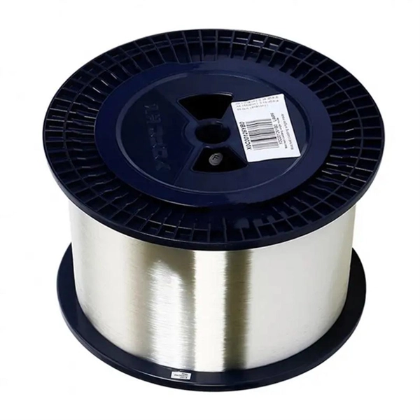
One of the core advantages of MPO patch cords is their high-density integration. Traditional patch cords have only 1-2 cores per cord, while MPO patch cords can integrate 12-48 cores, enabling multi-port connections with a single cord. Fiber cores are the heart of fiber optic cables, transmitting light signals that carry data. Made from either high-quality glass or plastic, the core plays a critical role in determining the cable's performance. The total number of cores for a 1pc fiber patch cable is calculated as the number of. Multi-core patch cords are fiber assemblies containing multiple fibers within a single cable jacket, typically available in 4, 6, 12, and 24-fiber configurations. The outer sheath is clearly marked with core count indicators. MTP/MPO cables are a class of high-density multi-core fiber optic connectivity solutions widely used in data centers and telecom networks, which are designed to achieve fast connection of multi-core fiber optics through a single interface. In the context of accelerating digitalization, the rational. The 16-core MPO patch cord, a high-density optical fiber connector, has become an ideal choice for 400G networks and beyond due to its superior optical performance, flexible compatibility, and efficient cabling capabilities. This report analyzes the key technical parameters, primary application.
[PDF]
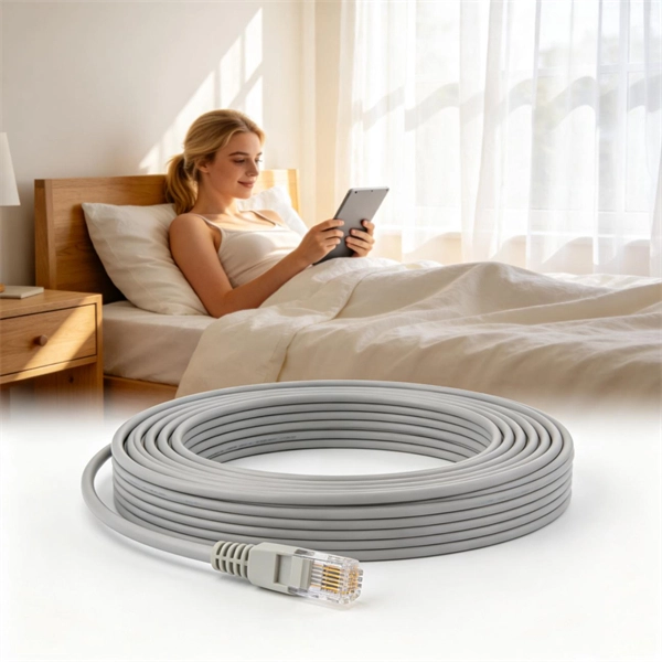
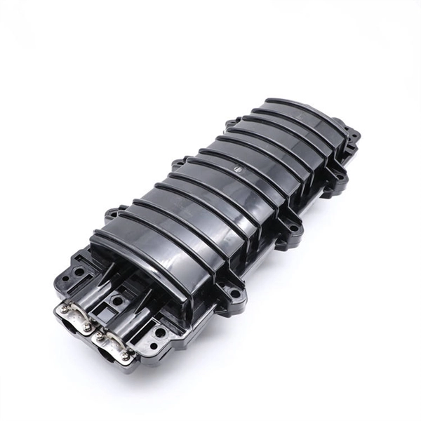
Step1 : Identify the optical cabinet and network operating center, and find the fiber optic splitter. Step 5: Patching from the splitter port to the user. Fiber optic patch cords must be installed correctly to ensure best network performance, reduce signal loss, and protect the sensitive fibers. Whether you're connecting a data center, a corporate network, or a high-density fiber infrastructure, correct installation methods are essential. Yingda. You can put in a fibre patch cord at home. You just need to follow easy steps and be careful. Planning helps you pick the right cord for your network. Be gentle when you handle the cord. Fibre patch cords last longer and are tougher than. This article will guide you through the necessary tools, materials, and methods on how to connect fiber optic cables effectively, ensuring you achieve optimal performance from your fiber optic network. Have a network installation project? Fiber Optic Cables: The primary medium for your connections. NS Comm provides enterprise-grade fiber optic patch cables engineered for maximum reliability and low-loss performance. However, proper installation techniques are essential to unlock their full potential. This guide will help you understand fiber construction, installation steps, real attenuation. Correct patch-cord installation is essential for maintaining low insertion loss, stable return loss, and long-term reliability in both indoor and outdoor fiber networks.
[PDF]

This guide covers the essential tools and step-by-step procedures for low-loss fiber optic cable repair. Understanding the causes and types of fiber optic cable damage helps detect issues early and determine when repair is needed. Construction Activities: Accidental damage during construction. Step1 : Identify the optical cabinet and network operating center, and find the fiber optic splitter. Step 2: Identify the splitter number. Step 4: Find the optical fiber port and cable sequence that leads to the user. 2) The. This complete guide covers everything from identifying causes of failure to advanced repair techniques, drawing on the latest industry standards and innovations. Whether you're a network technician, IT professional, or telecom operator, you'll find practical steps, tools, and tips to restore. If you accidentally break a fiber optic patch cord in your server room or in any of your switch gear, now you can repair it on the spot and get back up and running in minutes. Adhering to precise methodologies, we can mend impaired cables. By understanding these key elements and following the outlined steps, you can effectively repair fiber optic cables and maintain the high-performance network necessary for today's demanding communication needs. When it comes to ensuring nice network experiences for users, the condition of a fiber.
[PDF]

Bend insensitive fiber patch cable is designed to transmit light with minimum loss even if they are bent beyond the bend radius. Fiber optic patch cords are often treated as low-risk consumables, yet a large percentage of optical link failures originate at the patch cord level. Unlike backbone cables, patch cords are frequently connected, disconnected, bent, and handled by technicians, making them the most vulnerable. The bend radius of fiber cables is critical for maintaining high performance and longevity. During installation under tension, maintain a minimum bend radius of 20 times the cable's outer diameter, while post-installation requires a minimum long-term bend radius of 10 times the cable diameter. Fiber optic cables are designed to withstand some bending, but excessive bends can physically damage the glass fiber or cause significant signal loss. That's why every fiber cable has a minimum bend radius specification provided by the manufacturer. The minimum bend radius defines the smallest. When fiber optic cables are bent more sharply than recommended, the internal fibers can break or develop micro-fractures, leading to: Reduced Signal Quality: Noticeable deterioration in signal transmission, including lower speeds and data loss, often results from bending-induced damage. As the bending becomes more acute, more light leaks out (shown in the picture below).
[PDF]
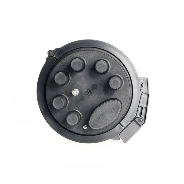
When choosing the best septic distribution box covers, consider options like the 12×17 Valve Box Cover Lid for sprinkler irrigation, the durable NDS Rectangular Valve Box Cover for septic systems, and the reliable Tuf-Tite 4-Hole Distribution Box. Each cover offers unique features, such as. BARR Plastics offers a comprehensive range of septic distribution boxes, modular risers, and lids, perfect for maintaining and upgrading your septic system. Our septic accessories, including durable septic products and riser kits, are designed to provide long-lasting performance. However, they may not withstand heavy loads. Concrete Covers: Known for their durability, concrete covers can handle significant weight and are less likely to be. Made in the USA - Flat Rate Shipping $17. 95! Pioneering filter technology since 1959 Zabel Environmental Technology® is the most recognized and trusted name in onsite wastewater filtration. Built with high-quality concrete, this lid provides a secure seal, preventing debris, water infiltration, and accidental access.
[PDF]

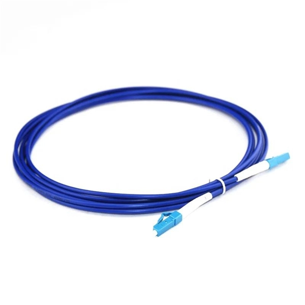
Multi-mode fiber optic patch cords utilize a larger core size, typically around 50-100 microns, allowing them to carry multiple modes of light. This design enables the transmission of data over relatively short distances with high bandwidth capabilities. A fiber-optic patch cord is a fiber-optic cable capped at each end with connectors that allow it to be rapidly and conveniently connected to telecommunication equipment. This is known as interconnect-style cabling. A fiber-optic patch cord is constructed from a core with a high refractive. These short fiber optic cords connect transceivers, switches, patch panels, and servers. Without them, even the best optical modules and switches cannot deliver performance. As data rates increase from 10G → 100G → 400G → 800G, patch cables must handle more bandwidth, more density, and stricter. Fiber optic patch cords, also known as fiber optic patch cables or fiber jumpers, are indispensable components in modern optical networks. They act as the critical link for interconnecting devices like optical switches, servers, and distribution frames. Understanding the various technical. Fiber patch cables, also called fiber-optic patch cords, are cables typically containing one or two optical fibers, which are equipped with standardized fiber connectors on both ends. The function of the fiber patch cord.
[PDF]
Our list for Fiber optic products suppliers in Ecuador is one of the most comprehensive in the industry. As of May, 2026, we have compiled data on 23 verified listings. Located in the Duran canton of the Guayas Province, at Km 9. **** ZC Mayoristas Matriz. ****. Our team of fiber optic specialists is always available to provide expert advice and tailored solutions, ensuring you get the best connectivity for your needs. As an Ecuadorian company with international standards, we deliver world-class fiber optic solutions while understanding the unique needs of. Our High Quality patch cable in Ecuador all through China regions along with other countries. They are selling to Southeast Asia, Japan, Korea, the Middle East and Europe. We use new technologies to produce High Quality patch cable in Ecuador items to achieve higher accuracy, high intelligence and.
[PDF]
smart Malaysia has announced the launch of smartCare, an advanced aftersales service program designed to ensure the roadworthiness of all smart vehicles and provide proactive support to existing smart owners. This comprehensive program encompasses a range of services and features aimed at. Your smart cars comes with an exclusive 8 years or 200,000km for high-voltage battery warranty assurance to give you peace of mind. The high voltage battery 8 Years assurance period is up to 8 years from the date of registration and fully covered by smart included vehicle must be serviced at every. Enquiries on dealer locations and product availability Smart Solar Water Heater Sales & Service Malaysia Email: info@ecosmart. my Smartsolar hot water heater system come with digital temperature controller that you can read the temperature and control the backup heater automatically.
[PDF]
For systems with fewer than 32 channels, a core switch is generally unnecessary. Basically, the core switch is not required under 50 channels, the second layer switch plus router can be used, and the 100-channel or so will use the efficient routing function of the core switch. First of all, the 100-channel monitoring belongs to a medium-sized network. His network is under. Many engineers also say that I can manage 300 cameras without a core switch, and that's fine! With 10 years of experience as a security R&D engineer, I will tell you how to configure a core switch for cameras. What is a core switch? A network has three layers: access, aggregation, and core. Generally, large enterprise networks and Internet cafes need to buy core switches to achieve robust network scalability to protect the original resources. We will use. Core switches and edge switches are two essential components that play distinct roles in the functioning of a network.
[PDF]
Explore all types of cable trays—ladder, perforated, basket, solid, and channel. Each cable tray type performs a different function and comes in various materials such as aluminum, galvanized steel, and FRP. What is Cable Tray? 1. Non-Metallic What is Cable. Cable tray systems are engineered support structures designed to route, support, and protect insulated electrical cables used for power distribution, control, instrumentation, and communication. Unlike conduit systems, cable trays allow cables to be laid in bundles, improving accessibility, heat. Below are the top 7 types of cable trays and their applications, along with their key advantages. Ladder Type Cable Tray The ladder type cable tray consists of two side rails connected by rungs, allowing excellent airflow around cables. Ladder cable tray is so named because it resembled a ladder. Ladder cable trays are relatively simple in. Selecting the correct cable tray for low voltage system—such as data networking, telecommunications, security, and building automation—is a critical decision that impacts system performance, scalability, and long-term reliability.
[PDF]

Ensuring Uninterrupted Power Supply: A UPS and DG monitoring system plays a vital role in ensuring uninterrupted power supply. It continuously monitors the power sources, batteries, and overall system performance. A UPS system provides temporary power during electrical outages or disturbances, acting as a bridge until the primary power source is restored or the DG system takes over. They are designed to deliver power instantaneously from energy stored in batteries, super capacitors, or a mechanical storage method. Sensitive electronics, such as computers. UPS or Uninterruptible Power Supply is vital protection against loss of data and costly hardware damage. It ensures that the network systems are operational when the main source of power fails. For home users, a UPS can protect desktop PCs, gaming consoles, and smart home devices from unexpected power cuts. In business settings. These monitoring devices, commonly known as RTUs, will send alerts back to vital personnel via LAN, phone voice message, serial connection, T1, fiber, or other available transport. In this way, organizations can track and log the voltage at the cell level, providing a good assessment of the overall. A 24V DC UPS can manage voltage fluctuations, frequency distortions. These short outages and provide a clean and reliable supply to the control system. With its backup battery pack, a DC UPS designed for an industrial environment will be more resistant to harsh external conditions.
[PDF]
The communication system of fiber optics is well understood by studying the parts and sections of it. The major elements of an optical fiber communication system are shown in the following figure. The ba.
[PDF]
By studying the expansion of Chinese telecommunications companies abroad, with a particular focus on Africa in our case study, the chapter aims to explore the relationship (i. partnership or/and competition) between African and Chinese telecommunications in. Chinese telecom infrastructure in Africa has expanded rapidly, embedding Beijing's influence into the continent's digital backbone. Upholding the principles of sincerity, real results, amity and good faith, China and African countries have achieved notable outcomes in infrastructure cooperation. Africa is China's. Chinese involvement in Africa's telecoms sector predates the DSR. The global advance of Chinese telecommunications firms, such as Huawei and Zhongxing Telecom Ltd (ZTE), was largely enabled by China's “go out policy,” which was launched in 1999 with the aim of promoting the internationalization of. According to the Tech Review Africa and Chinese Xinhua News, China Mobile officially activated 2Africa East Segment Submarine Cable on November 7, 2025, with an aim to power digital transformation across the African continent. The 2Africa submarine cable system, which spans 33 countries across. Infrastructure cooperation between China and Africa is thriving, and the outcome is changing the lives of millions. Industrial leaders and officials observed that the infrastructure projects undertaken by Chinese companies have yielded tangible benefits for Africans, helping the continent enhance.
[PDF]