Rodent damage in underground or aerial installations. Symptoms: Gradual performance decline over months/years. UV exposure degrading jacket materials. Use Case: Identifying macrobends, breaks, or sharp bends in. In the high-stakes world of optical networking, even a minor disruption in a Pigtail Fiber connection can cascade into costly downtime, affecting data centers, telecom services, or industrial systems. This article equips engineers and network operators with actionable strategies to diagnose. Fiber pigtail failures can lead to unexpected signal loss, link instability, and repeated maintenance. Understanding how to identify early warning signs can help reduce downtime and protect your network from unnecessary failures. A visual check is often the first step when diagnosing a defective. However, when signal loss occurs in a 12 fiber pigtail, it can lead to disruptions in network performance, such as decreased data transfer speeds, increased error rates, or even complete outages. Understanding the potential causes of signal loss and implementing effective troubleshooting methods is. Executive Summary: A fiber optic pigtail is one of the most commonly specified yet least understood components in structured cabling. Dust or oil contamination leads to signal loss. Always clean fibers before splicing. Using the wrong connector (LC vs SC) can cause compatibility.
[PDF]

Regularly testing fiber optic cables helps minimize network downtime, lengthens the network's longevity, reduces maintenance requirements, and helps support network reconfiguration and upgrades. Fiber optic testing ensures the performance and reliability of fiber optic networks. Key tests include: Effective fiber testing utilizes advanced tools such as Optical. Fiber optic testing for continuity is crucial in ensuring that light transmits through fiber optic cables without interruptions, safeguarding seamless data transmission. This guide talks about the primary methods and tools for effective continuity testing in fiber optic cable networks. Insertion loss testing confirms whether the cable meets design loss budgets. OTDR testing identifies events along the fiber length, including: OTDR is essential for long-distance FTTH feeder and distribution cables. After the cables are installed and terminated, it's time for testing. For every fiber optic cable plant, you will need to test for continuity, end-to-end loss and then troubleshoot the problems. If it's a long outside plant cable with intermediate splices, you will probably want to verify the. We'll explain why it's vital to test fiber optic cables, the three most popular methods, and when you should use them. Why Testing Fiber Optic Cables Matters? Regular testing of fiber optic cables is not just a preventive measure; it's an.
[PDF]

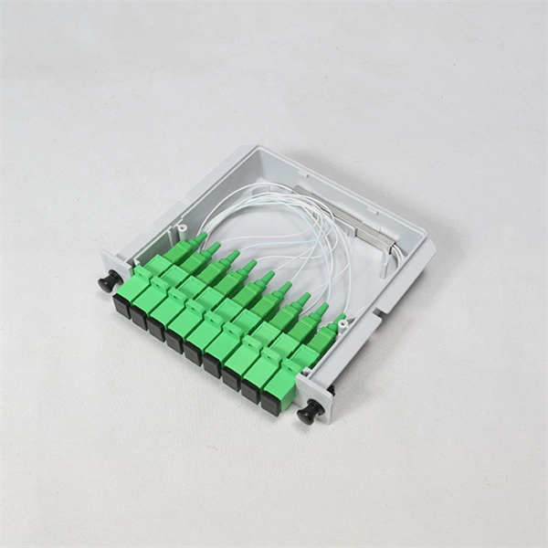
However, essentially, optical fiber patch cords are more like "finished connection lines", while optical fiber pigtails are "semi-finished connectors". The difference in this core positioning determines the vast disparity between them in structure, connection methods. Executive Summary: A fiber optic pigtail is one of the most commonly specified yet least understood components in structured cabling. Get the wrong connector type, the wrong polish, or skip proper fusion splicing technique—and you're looking at elevated signal loss, increased back reflection, and a. When you build or upgrade a fiber network, the same four words pop up everywhere— fiber optic (bare fiber), pigtail, patch cord, optical cable. They're related, but they are not interchangeable. Mixing them up drives costs higher, increases loss, and slows your rollout. The good news? Once you nail. A fiber pigtail is typically a fiber optic cable with one end factory pre-terminated fiber connector and the other exposed fiber. It is usually suitable for field termination using a mechanical or fusion splicer. The connector end plugs into devices like transceivers or patch panels, while the bare end is typically fusion spliced to a fiber optic cable. This setup ensures. As outlined in T13: Fiber Optic Fundamentals, an optical fiber is a coaxial cylindrical dielectric waveguide with a core refractive index exceeding that of its cladding.
[PDF]
Optical pulses traveling through multimode optical fibers encounter the influence of both linear disturbances and nonlinearity, resulting in a complex and chaotic redistribution of power among different modes. I.
[PDF]
The state of a laser's polarization is determined by several anisotropic mechanisms of either the laser gain media or the resonator. "Anisotropic" refers to properties whose values vary in different direct.
[PDF]

Optical isolators utilize retarders to prevent unwanted reflections, while optical attenuators adjust light intensity by varying polarization alignment. Polarization rotators and variable beam splitters allow controlled redirection of light for applications in optical systems and. Thorlabs offers an all-in-one attenuator that will reduce brightness as well as accentuate contrast. This gives the user much finer control of the image brightness compared to a standard fixed-transmission filter. When the polarizer transmission axes and input polarization are parallel, the. We propose and demonstrate a polarization-insensitive silicon photonic variable optical attenuator. The designed device uses a two-dimensional apodized grating coupler as a surface-normal coupling interface, which has the advantages of low-cost fiber packaging and polarization insensitivity. Boston Applied Technologies' Polarization Maintaining Variable Optical Attenuator (PM-VOA) maintains constant polarization output regardless of wavelength and level of attenuation. Based on the. MEMS attenuators (MEMS VOAs) are based on a micro-electro-mechanical system (MEMS) technology. It is a micro-optic component designed for next generation, dynamically configurable optical networks. The. Figure 1. 1 For narrowband VOAs, turning the adjustment screw moves the blocking device up and down in order to achieve the desired attenuation.
[PDF]

Use two fibers: one dedicated to TX, the other to RX. Both sides transmit and receive at the same wavelength (common values: 850 nm MM, 1310 nm/1550 nm SM). The front panel is usually labeled TX and RX, and you cross-connect TX→RX, RX→TX with a duplex patch cord. Switch optical port intercommunication means that the optical fiber ports of two switches are connected to each other to achieve the purpose of network connection. The connection between two or more Ethernet switches in a certain way (Uplink port, etc. ) is called the cascade. SFP modules insert into these slots and and require two strands of fiber, typically duplex Using multi mode fiber (for runs under 1000 feet) or duplex single mode fiber (for runs over 1000 feet). This is a cost-effective and high performance way to connect network switches. Use one fiber strand for both. The switch supports 10 Mbps, 100 Mbps, and 1000 Mbps connections. Using Gigabit Ethernet (1000 Mbps), the switch sends files across the network at speeds up of to 2000 Mbps due to the full-duplex nature of Gigabit Ethernet connections. You can either connect 24 Ethernet copper cables or 22 copper. Port types are limited to two: optical and Ethernet. Optical ports on switches typically accommodate optical modules for transmitting data via fiber optic cables. In situations where there's a shortage of Ethernet ports, some users may insert Ethernet port modules into optical ports to connect with.
[PDF]