
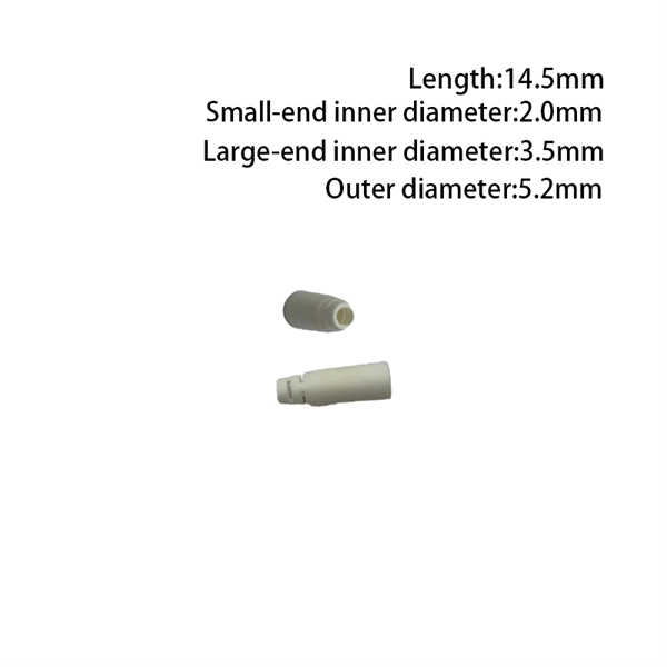
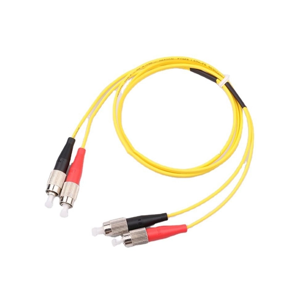
FiberMall MPO16 APC Y Splitter Cables 10m are designed for 800G QSFP-DD/OSFP DR8/OSFP XDR8 optics direct connection and support 800G transmission for Hyperscale Data Centers. Multimode PLC Splitter is a passive optical device used to split incoming signals into two or more output signals. They're capable of operating over a broad wavelength range from 650 nm to 1350 nm (Typ. 650nm, 850nm and 1300/1310nm). 5/125 (OM1, OM2, OM3 and. High-Quality Construction: This Fiber Optic PLC Splitter is manufactured by UT-KING, a reputable brand known for its reliable products, ensuring a durable and long-lasting performance. Optimized for FTTH Solutions: Designed for use in Fiber-to-the-Home (FTTH) applications, this 1x2 OM3 PLC Splitter. Optical coupler is an optical device that combines or splits power from optical fibers. Note: All insertion loss and insertion loss referenced without connectors. Takfly, established in 2000, has been manufacturing. Optional split ration 1:99, 2:98, 5:95, 10:90, 20:80. USource OM3 Fiber Coupler is a 1x2 or 1x3 passvie optical multimode splitter based on FBT (Fused Biconic Taper) technology, packaged in mini ABS box module or steel tube, split into different rations 1:99, 2:98, 50:50, 10:90, 20:80.
[PDF]
Every temporary power distribution box has several important components that work together to deliver safe, efficient power: These boxes use either 120/240 VAC single-phase or 120/208 or 277/480 VAC three-phase power sources. Temporary power distribution boxes are a budget-friendly way to supply electricity to a remote area. You can use them to power electrical equipment, lighting systems and more. Compared to other temporary power solutions, a power distribution box provides utility, safety and efficiency at an. Temporary power distribution boxes provide a safer way to manage power while keeping your workspace tidy. These versatile units work great for construction sites, entertainment events, and disaster recovery operations. Modern solutions rely on portable. Whether you need an industrial portable power station, a complete jobsite power station, or help managing temporary wiring and distribution, this will help you stay compliant with all the necessary requirements. Getting the selection wrong means more than inconvenience—it can mean shutdowns, damaged machinery, or worse.
[PDF]
UAE's top 10 manufacturers and suppliers of power transmission and distribution products. Utilities. M-Tech International is a prominent manufacturer and distributor of electrical equipment, focusing on oil immersed and dry type distribution transformers, as well as medium and low voltage switchgear. Electrical Distribution System | M-Tech (Multi Technology) Pvt. Limited ADC Energy Systems ADC is. Leading suppliers and manufacturers of Power Distribution Box in the UAE and Dubai. Our high-quality Power Distribution Box are ideal for various industrial applications. Schneider Electric UAE is a trusted name in the UAE's power sector, offering a diverse array of transmission and distribution equipment designed to enhance efficiency and reliability. From medium voltage switchgear to advanced grid automation solutions, Schneider Electric Gulf empowers businesses. products_backup can be pr. No change to the cabinet. Designed for easy transport and setup, these boxes feature premium breakers and connectors for reliable performance. Our selection. SAS Power is one of the leading providers of customized power and automation systems, power distribution equipment, comprehensive solutions in energy –transmission, distribution & automation & water sector and the supply of related field services. Lighting up your world with superior, made-to-order.
[PDF]
Our platform offers reliable and verified trade intelligence across major Power Distribution Cabinet exporting and importing nations. Each record includes HS Code classification, shipment value (FOB/CIF), quantity, port of origin/destination, and exporter-importer. For factory and warehouse operators across Southeast Asia, the 380V power distribution cabinet serves as the backbone of electrical infrastructure. However, the term "380V" is often used as a shorthand for a range of three-phase industrial voltage standards that vary by country. Understanding these. Products such as power distribution cabinets, control panels, and low and high voltage switchgear must meet project standards and local requirements. One of the key advantages of working with an experienced supplier is their ability to handle international projects. This includes understanding. This report provides a detailed analysis of the global distribution box market, including supplier landscape, key technical specifications, and essential quality certifications. The information is compiled from recent market analyses and supplier data to guide sourcing decisions. Our global Power. China Top Ex. Discover New & profitable Power distribution cabinet buyers & suppliers, Access 16,988 export import shipment records till Dec - 23 with 2,138 importers & 2,159 Exporters.
[PDF]
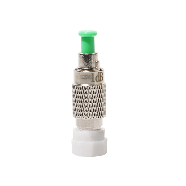
Diagram showing positive tip polarity on the left and negative tip polarity on the right. To read diagram: The center positive drawing on the left indicates that the center (also known as the tip) of the output plug is positive (+) and the barrel (ring) of the output plug is negative. The center positive drawing on the left indicates that the center (tip) of the output plug is positive (+) and the barrel of the output plug is negative (-). Symbol for a center-positive power supply. It is always good practice to test. The term positive terminal describes which of the two connection terminals on direct current (DC) equipment supplies or is meant to receive a positive electrical charge. DC power supplies always feature a positive to negative electron flow and always have a negative and positive terminal. Polarity. It is defined by the positive and negative terminals of a power source, such as a battery. Understanding polarity is essential because connecting a device to a power source with the correct. The rating plate of an Extra Low Voltage Power Supply (ELVPSU) shows various symbols and abbreviations. These represent critical information about the supply's ratings, class, polarity, and other safety details. The polarity symbol indicates if the centre (or tip) of the output plug is positive (+).
[PDF]

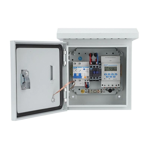
A distribution box, also known as a distribution panel or board, is a cabinet that holds electrical parts used to supply power to multiple circuits within a system. It acts as the central point where electricity distribution is managed inside a building. It helps organize, protect, and control electrical connections in residential, commercial, and industrial electrical systems. Distribution. A distribution boxes is an essential device that manages the safe and efficient flow of electrical power throughout different areas of a building or facility. It is commonly used in homes, offices, and industrial settings to control and protect electrical circuits. Without it, managing power would be messy, unsafe, and inefficient. It typically contains essential components such as circuit breakers, surge protectors. The main power line connects to a distribution box, which then distributes the electrical power. They receive electrical power from. Every industrial or commercial facility depends on a reliable and well-regulated electrical system. At the heart of this network lies a power distribution box, the component responsible for dividing and controlling electricity as it moves from the main source to multiple end-use circuits.
[PDF]

Professional installation available nationwide across the Philippines. 100% genuine products from authorized distributors with full warranties Free delivery to major cities, professional installation available Technical support and consultation from certified solar engineers. Professional installation available nationwide across the Philippines. Buying Distribution Box For Solar Set Up with great prices online? Nasa Lazada Yan! The top online shopping platform in the Philippines always boasts a great assortment. Get a ₱50 voucher if your order arrives late. IP65 design, waterproof, anti dust and anti ultraviolet. Strict test for high and low temperature, used widely. The simple installation, the simplified system wiring, the convenient wiring. Used for single crystal silicon solar modules, polycrystalline. In Metro Manila, the continuous rise of commercial high-rises, BPO (Business Process Outsourcing) centers, and mixed-use developments in areas like Bonifacio Global City (BGC) and Makati requires robust and highly reliable electrical distribution networks to ensure zero downtime. On the industrial. Premium solar panels, inverters, and components from trusted international brands. They offer a range of services, including the development of solar farms and grid-tied rooftop. Sale! © 2026 Solar Hub PH.
[PDF]

The core measurement procedure follows five steps: Turn on the meter and let it warm up. Most meters need a brief stabilization period before readings are reliable. Check your model's manual, but a minute or two is typical. Set the wavelength to match your light source. Fiber loss is the difference between the power when light is coupled from the transmitting end to the fiber and the power when the light reaches the receiving end. Generally speaking, when measuring the. An optical power meter measures the strength of light traveling through a fiber optic cable, giving you a reading in dBm (decibels relative to one milliwatt). The basic process is straightforward: turn the meter on, set it to the correct wavelength, clean your connectors, plug in, and read the. A power meter and light source are essential test tools that work in tandem to measure fiber optic cable loss and evaluate the quality of optical links. They provide the data necessary to quantify signal loss and pinpoint issues that could impact network performance. Here's how they work: A power. You measure optical power in dBm or insertion loss in dB. Verify light travels from transmitter to receiver. We'll give you the basic information you need and provide some printable references.
[PDF]
Silicon photonics is transforming AI computing by enabling energy-efficient, high-speed data transmission. Discover how optical interconnects present a possible solution to the data center energy crisis and drive sustainable innovation. Lam Research is setting the agenda for the wafer fabrication equipment industry's approach to a silicon photonics revolution, driving the breakthroughs in Specialty Technologies that will enable sustainable AI scaling through precision optical manufacturing. The artificial intelligence boom has. y with vastly reduced energy con-sumption by integrating optics deeply within computing sockets. We present the design and characterization of a dense wavelength-division multiplexing (DWDM) SiPh transceiver chip, featuring a unique architecture in the multi-FSR regime and targeting a shoreline. Silicon photonics is becoming a critical enabler of AI and HPC, breaking the limits of electrical interconnects in bandwidth, distance and power efficiency. Co-packaged optics (CPO) builds on silicon photonics, with SiPh transceivers as the integration platform and CPO as the packaging architecture. Silicon Photonics emerges as the solution to this predicament, replacing electrons with photons—the fundamental particles of light—to race across familiar silicon-based chips, promising a revolution in computing and communication. This isn't just about increased speed; it's about a profound impact.
[PDF]
Built on Huawei's unified software platform and equipped with high-performance fully programmable chips, they deliver abundant features including Service Roam, VXLAN and iFlow, helping customers build high-quality campus bearing networks for the all-wireless era. Leveraging the Service. CloudEngine S5735-S-V2 switches support simplified operations and maintenance (O&M), and flexible Ethernet networking. It also provides enhanced Layer 3 features and mature IPv6 features. For example, it can be used as an access or. CloudEngine S5736-S series switches are next-generation standard all-optical GE access switches that provide 24-port and 48-port models, and provide four 10GE ports and one extended slot(optional). CloudEngine S5736-S series all-optical GE access switches are developed based on next-generation. Comprehensive analysis of Huawei's revolutionary optical switch innovations for 2025, including data center all-optical switching, silicon photonics integration, quantum-compatible switches, and 5G-Advanced network solutions. The port supports the PoE function. It sends and receives service data at 1000 Mbit/s or 10 Gbit/s.
[PDF]
Designed for factories, commercial buildings and distributed solar projects, this 50kW / 100kWh C&I energy storage system delivers reliable peak shaving, backup power and intelligent energy management in one integrated cabinet. With high-voltage LiFePO₄ batteries, 4 MPPT hybrid inverter and. PowerCore 50kW/100kWh Energy Storage System, engineered for seamless, solar-driven resilience across homes, farms and industrial sites. 20A PV input current per string, compatible with all PV modules. 4 MPPTs and 200% PV oversizing ensure maximum utilization of solar energy. 280Ah long-life. The Energy Cube 50kW/100kWh is a fully integrated commercial and industrial energy storage solution combining battery modules, BMS, PV inverter, fire protection, distribution, thermal management, and energy management systems. It enables independent microgrid operation by directly connecting PV. Explore the innovation Product Center and open up a new future for green energy This product is a modular converter specifically designed for small energy storage systems, with a rated power of 50kW. It combines high-efficiency solar power generation with advanced lithium battery storage to ensure stable, reliable, and cost-effective energy supply. It includes 7 battery packs ( 280Ah, 3,2V Cell), Battery Management System (BMS), 1 hybrid inverter, fire protection system, AUX distribution system.
[PDF]
At Multilink, we offer traffic power solutions to keep traffic signals, camera equipment, illuminated street signs and other tech up and running. Power traffic signals, camera equipment, lighting and other t.
[PDF]

Learn how to monitor SFP optical power on Cisco switches, interpret Tx/Rx levels, and troubleshoot fiber link issues. Step-by-step CLI commands, model-specific guidance, and best practices included. In this article, we will break down the key factors influencing TX/RX power, explain how to calculate the optical power budget, and provide actionable insights for optimizing your network's performance using SFP modules. SFP (Small Form-Factor Pluggable) modules are compact transceivers that allow. SFP (Small Form-factor Pluggable) optical modules are compact, hot-pluggable transceivers that enable network equipment to connect seamlessly to fiber and copper links. Even if an interface appears up, degraded Tx/Rx levels can cause intermittent flapping, packet loss, or err-disabled states. Think of it as the “translator” for your network equipment, converting electrical signals into optical signals. The most two important factors of the SFP transceiver: Output power (TX power) and receiver sensitivity (RX sensitivity). The optical TX power is the signal level leaving from that device, which should be within the transmitter power range. The RX sensitivity is the incoming signal level being. In current network communication, SFP optical modules are an indispensable physical foundation for building network channels. They form high-speed channels for optical signal transmission. Therefore, to ensure their.
[PDF]
Whether you're building a commercial setup or upgrading an industrial plant, proper cable tray installation ensures neat wiring, safe access, and easy maintenance. But before you lay the first tray or clamp down a single cable, you need a solid plan. This guide breaks. This method statement covers the site installation of the cable tray & ladders and the requirements of checks to be carried out. The Cable Tray system is installed in electrical rooms, plant rooms, and service corridors. This guide breaks down the process step by step. This process is integral to determining the optimal arrangement and configuration of cable trays, which are essential for routing and supporting electrical cables within buildings and. 1. 0 This method statement will serve as a minimum guideline to carry out the Cable Tray Installation activities for commercial buildings, plants and refineries in accordance with Project Drawings and Specifications. This document outlines the key requirements for cable tray layout, installation, and fireproofing in industrial and commercial environments. Route. Below is the detailed cable tray installation method statement not only for cable tray but also applicable for GI ladder and trunking for indoor and outdoor applications and in service rooms like pump rooms, electrical rooms and plant rooms etc. All materials intended for cable tray, ladder and.
[PDF]

In this video, we'll show you how to connect an energy meter to a distribution board (DB) safely and efficiently. energy meter connection with distribution box How to Connect an Energy Meter to Your Distribution Box Easily Steps to Properly Connect Your Energy Meter to a Distribution Box. It plays a vital role in ensuring the safe and efficient distribution of electricity throughout the premises. What is the wire from the meter to the breaker box? Also. Always begin with disconnecting the main supply before accessing any enclosure containing distribution components. This prevents arc faults and ensures safety when modifying or inspecting current paths. This “meter to panel” wiring establishes the pathway for all incoming electrical power from the grid to the home. Its primary function is to safely and reliably. Distribution Board aslo know as “Panel Board”, “Switch & Fuse Board” or “Consumer Unit” is a box installed in the building containing on protective devices, such as circuit breaker, fuses, isolator, switches, RCDs and MCBs etc. The electric main supply (230V AC & 120V AC in US) is connected through. Changed Texas's reference diagram for the 3 wire network 120/208 Volt single phase self-contained Revised Figures 13, 14, 14b. Limited the meter location from pad mount transformer for PSO. Removed unistrut being listed as an alternative means for mounting the meter box. APCo and TX do not allow.
[PDF]
