Diagram showing positive tip polarity on the left and negative tip polarity on the right. To read diagram: The center positive drawing on the left indicates that the center (also known as the tip) of the output plug is positive (+) and the barrel (ring) of the output plug is negative. The center positive drawing on the left indicates that the center (tip) of the output plug is positive (+) and the barrel of the output plug is negative (-). Symbol for a center-positive power supply. It is always good practice to test. The term positive terminal describes which of the two connection terminals on direct current (DC) equipment supplies or is meant to receive a positive electrical charge. DC power supplies always feature a positive to negative electron flow and always have a negative and positive terminal. Polarity. It is defined by the positive and negative terminals of a power source, such as a battery. Understanding polarity is essential because connecting a device to a power source with the correct. The rating plate of an Extra Low Voltage Power Supply (ELVPSU) shows various symbols and abbreviations. These represent critical information about the supply's ratings, class, polarity, and other safety details. The polarity symbol indicates if the centre (or tip) of the output plug is positive (+).
[PDF]

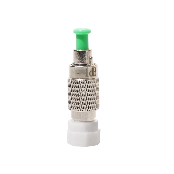
Optical return loss is the amount of light that is reflected back to the source, this reflected light is measured at each connector and splice at each point over the entire fiber link. This is always measured in dB (decibels) and will be displayed as a negative number. The closer the number is to. The polish of a singlemode fiber endface plays a significant role in reflectance. Understand what you need before you specify. The Institute of Electrical and Building the ORL story Electronics Engineers (IEEE) recently Within a fiber-optic channel or path-released new specifications within way. Optical Return Loss (ORL) in fiber optics refers to the amount of light that is reflected back toward the source in a fiber link. ORL is usually expressed in decibels (dB) as a positive value, with. Return loss (RL) is also called reflection loss. When high-speed signals enter or exit a part of an optical fiber, such as an optical fiber connector, discontinuity and impedance mismatch may cause reflection, which is the return loss of an optical fiber. Poor ORL is commonly caused by dirty connectors, poor splices, mismatched connector types, or damaged fibers. ORL is measured using ORL meters. Home Coherent Optics Optical Return Loss (ORL) Explained Comprehensive Guide to Understanding and Managing Back-Reflections in Fiber Optic Systems What is Optical Return Loss (ORL)? Optical Return Loss (ORL) is a critical parameter in fiber optic systems that quantifies the amount of light.
[PDF]
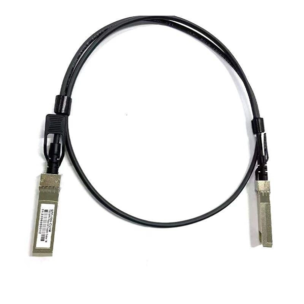
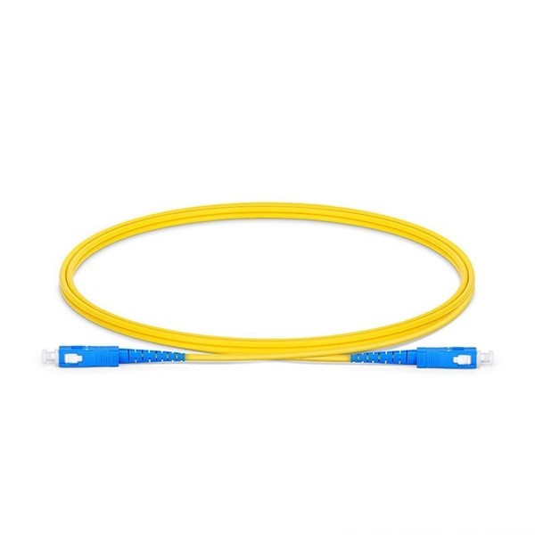
Fiber optic patch cords do not have “polarity” in the sense of electrical positive and negative terminals, like a battery. Plugging them in “backwards” will not cause a short circuit, and it will not burn out or damage your equipment. Patch cord polarity defines the directional optical path between two transceivers, ensuring that the transmit (Tx) signal from one device reaches the receive (Rx) port of the other. Patch cables for fiber optic can have the same connector on each end (e. Since fiber optic links require a two-way - or duplex - connection, there is potential for errors in installation by connecting transmitter to transmitter or. As networks move to higher speeds and higher density, choosing the right fiber optic patch cords becomes critical to the reliability of your system. At ZION Communication, we design and manufacture a full range of fiber patch cords for: This guide will help you quickly understand the main types of. Negative poles have a greater number of electrons relative to positive poles; when connected, electric current will flow from negative to positive. When used in the context of fiber-optic communication, this is analogous to the flow of data in the form of light signals from transmit (Tx) to receive. Simplex optics: A single fiber is used to plug things in and establish transmit and receive one one fiber in one direction. Parallel optics: Multiple fibers used to establish higher.
[PDF]
Fiber optic pressure sensors operate based on the principle of light modulation in optical fibers. When pressure is applied to the sensing element, it changes the properties of the fiber, such as the refractive index or the intensity of the light. These sensors are gaining popularity. Fiber-optic sensing (FOS) technology has emerged as a cutting-edge research focus in the sensor field due to its miniaturized structure, high sensitivity, and remarkable electromagnetic interference immunity. Compared with conventional sensing technologies, FOS demonstrates superior capabilities in. This article explains the structure, working principle, advantages, and disadvantages of Fiber Optic Pressure Sensors. Compared to traditional electronic pressure sensors, they offer advantages such as immunity to. Fiber optic pressure sensors are transforming how industries monitor and manage critical systems. Unlike traditional sensors, these devices use light to measure pressure changes, offering high accuracy, immunity to electromagnetic interference, and durability in harsh environments.
[PDF]
The communication system of fiber optics is well understood by studying the parts and sections of it. The major elements of an optical fiber communication system are shown in the following figure. The ba.
[PDF]
An optical spectrometer (spectrophotometer, spectrograph or spectroscope) is an instrument used to measure properties of over a specific portion of the, typically used in to identify materials. The variable measured is most often the of the light but could also, for instance, be the state. The independent variable is usually the of.
[PDF]

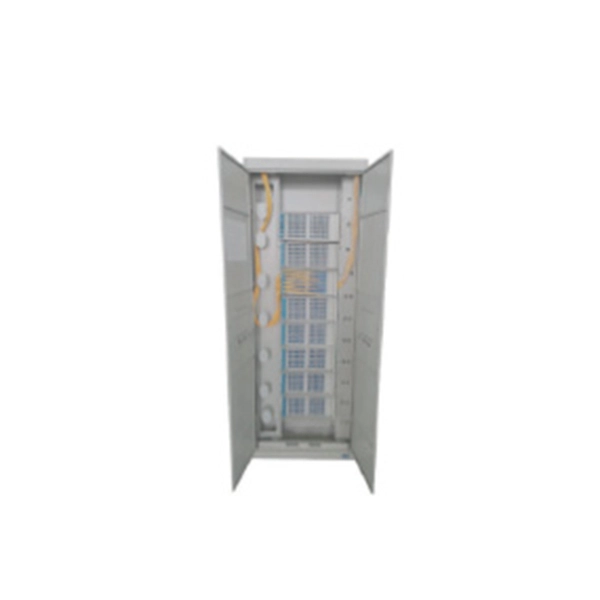
Networks are fundamental to the operation, security and resilience of many organisations. This guidance provides an introduction to the key topics to consider when designing, maintaining, or using networks that need to be secure and resilient. Network security combines policies and technologies to protect systems and digital assets from unauthorized access, misuse, and disruption. By using layered defenses rather than a single control, it ensures data integrity and reliable performance across increasingly complex, distributed networks. Modern IT infrastructure is comprised of various interconnected network components that make communication and resource sharing possible throughout your organization. It ensures systems remain confidential, available, and trustworthy across all digital environments. Its features are: Network security works through multiple protective layers that control. Part of the Cybersecurity Skills Guide — This article is one deep-dive in our complete skills and certifications series. By HADESS Team | February 28, 2026 | Updated: February 28, 2026 | 12 min read Network security fundamentals form the base layer of every cybersecurity specialization. It will also help you apply the NCSC's Cyber security. The foundation of effective network security rests upon several key principles. Each principle is essential in formulating a comprehensive approach to securing a network. (Issa) Confidentiality ensures that sensitive.
[PDF]