Parallel connection: A more common method involves connecting capacitors in parallel with the load. This facilitates more adaptability in modifying the capacitance to align with the fluctuating reactive power requirements of the load. Capacitor banks: Multiple capacitors can be grouped together to. Capacitors in parallel are ubiquitous in digital and analog hardware. When used properly, they increase capacitance, reduce unwanted impedance and noise, and improve power integrity across a broad frequency range. Capacitance adds in parallel, increasing total capacitance, since voltage is shared. In the following articles, we will explain the rationale behind connecting capacitor bank in parallel for power factor correction, discuss the consequences of series. Several capacitors can be connected together to be used in a variety of applications. Multiple connections of capacitors behave as a single equivalent capacitor. Walk into any design review where someone is questioning the power delivery network, and within five minutes someone will draw capacitors in parallel on a whiteboard. It's one of the most common configurations in electronics — and also one of the most misunderstood. The formula is dead simple, but. Figure 1: Basic capacitor network configurations showing series and parallel combinations Professional Tip: Always identify series and parallel sections separately before attempting to calculate the overall equivalent capacitance.
[PDF]
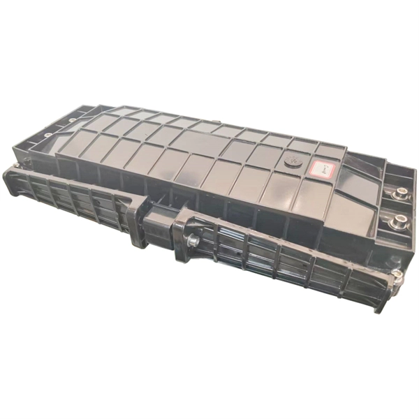
It emphasizes the importance of considering mechanical and environmental aspects, referring to the IEC 60794-2 series for technical specifications. The document details the characteristics of optical fibers and cables, including transmission, microbending and macrobending. Nowadays, optical communications are the most requested and preferred telecommunication technology, due to its large bandwidth and low propagation attenuation, when compared with the electric transmission lines. Besides these advantages, the use of optical fibers often represents for the telecom. As environments are becoming increasingly harsh, the ability of optical fiber cable to withstand such environments is of the utmost importance to outside plant users. Laboratory accelerated aging environments have long been used as a measure to predict field performance of optical fiber and cables'. This study investigates the strain transfer mechanism for different types of fiber optic cables while embedded in concrete cubes, sustaining a boundary condition which features a displacement discontinuity. The strain transfer mechanisms for different cables are compared under increasing strain. This document outlines the recommendations for single-mode optical fiber cables used in telecommunication networks within buildings, focusing on their mechanical and environmental characteristics. It specifies that these cables must comply with standards such as ITU-T G.
[PDF]
Appropriate Ethernet cables must be used to connect with the PoE and normal switch by means of a physical connection. Use the cables correctly and plug each end cable to the corresponding port on each switch to provide stable networking. So, the PoE switch is a networking device through which the PoE passes. In addition, this switch has numerous Ethernet ports that link to network segments, which also help with power and data. Can I use a PoE switch as a regular switch? (Answered) A POE switch gives power to devices that support the protocol, like cameras and access points. A regular switch, on the other hand, merely supplies the internet signal. A regular. A PoE switch simplifies network installation by providing power and data transmission over a single Ethernet cable. However, to take full advantage of a PoE switch, it's crucial to understand how to use it properly. This eliminates the need for separate power adapters, reducing cable clutter and. Just reuse teh POW cables that are alredy up there, and instead of them connecting to POE Wifi adapters, connect them to a POE switch (which would also allow me to add more cameras later) and drop a line from that switch into the main switch in the house. In this article we will uncover the subject matter of PoE switches and watch how they are necessary for the network design.
[PDF]

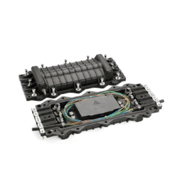
Summary : Fiber optic cables use light pulses to transmit data through ultra-thin glass or plastic strands, offering high-speed, long-distance communication. These cables rely on components like the core, cladding, strength member, coating, and outer jacket. These systems transmit digital information as rapid pulses of light through incredibly thin strands of pure glass, rather than as electrical current through metal wires. Multimode fibres operate primarily at 850 nm and sometimes at 1300 nm slightly different speeds. This is how optical prisms work Note: Forward Error Correction (FEC) is used to maximise link length for a given bit error. Optical fiber communication systems have become the cornerstone of modern telecommunications over the past four decades. As the demand for high-speed, high-capacity data transmission continues to grow exponentially, these systems have become increasingly essential. Harnessing the power of light. This is the FOA's Online Guide To Fiber Optics, Fiber Broadband & Premises Cabling. They operate on the principle of total. Designing a fiber optic network is like planning a city's road system, it needs to be efficient, reliable, and built to handle both current and future traffic. This fundamental aspect of modern infrastructure connects our homes, businesses, and communities to the digital world. Whether you're new.
[PDF]
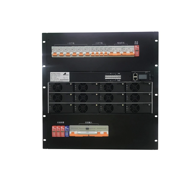
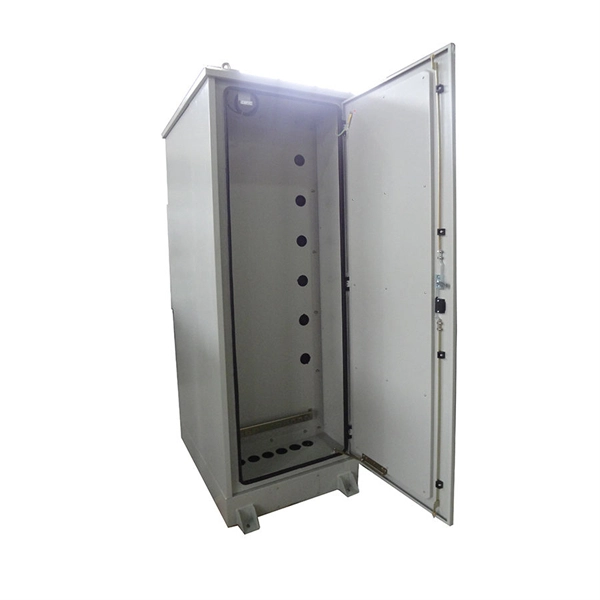
The panel box contains a series of circuit breakers or fuses that control the distribution of electrical energy to individual circuits throughout the building. An electrical panel box, also known as a breaker box or a distribution board, is a crucial component of any electrical system. It serves as a central hub for distributing electricity throughout a building, ensuring that power is delivered safely and efficiently to all the required locations. In this article, we'll explain what a series circuit is, how to draw a series circuit diagram, calculate. A distribution board or distribution box is where the main power supply is distributed to multiple loads. And all the switching and protective devices are installed in the distribution box. Single Phase Distribution Box generally consists of Double Pole MCBs, Single Pole MCBs, and RCCBs. Distribution. STEP 1: The flow of electricity begins at the g nerating station. at S the ation Switchyard. This is done to minimize the losses. STEP3: The ransmission Substation, increases the step-up voltage transformer from 69,000 to 765,000 volts. The distance it will go and the type of facilities distributed.
[PDF]