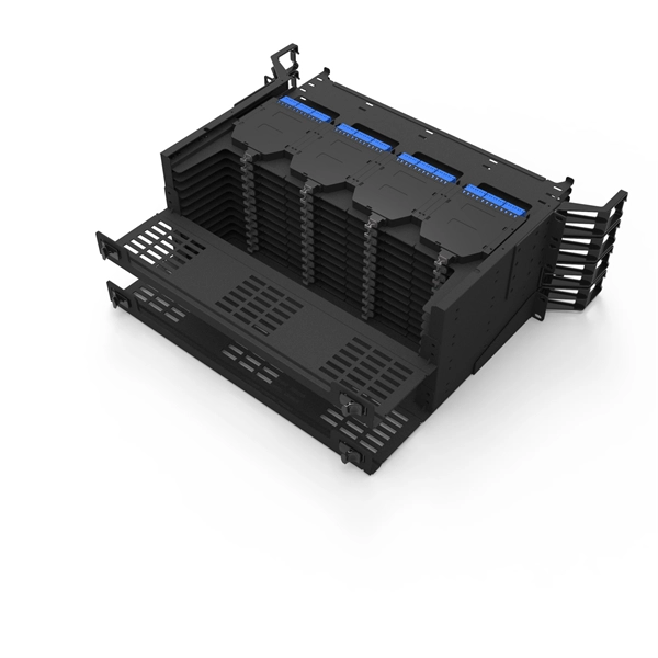
A well-chosen patch panel not only organises your fibre connections but also provides protection and flexibility for future expansions. In this comprehensive guide, we'll explore the key factors to consider when selecting the perfect patch panel for your network infrastructure. Choosing the right fiber optic patch panel is one of the most important decisions you'll make when building or upgrading a fiber network. While patch. Whether you're planning to upgrade your home internet connection or just curious about how fiber technology works, understanding the essential fiber optic equipment is the first step. From the optical network terminal to the router that brings your home online, each piece plays a critical role in. Structured wiring begins with a structured networking panel. These panels have ports for input cables and output cables. The right structured wiring can deliver top performance from your electronics. The panels accept cable from outside providers to distribute the signals to each room of your home. If you already know what your project requires, check out our complete Fiber Patch Panel selection. What is a Fiber Patch Panel? Fiber optic patch. Fiber optic installation is the way to go! It's super reliable and perfect for streaming, gaming, or using multiple devices. This guide breaks down the process in easy steps so you know what to expect. Aerial Service Drop: A cable coming from a pole to your house, connected at a small box called an.
[PDF]

Arduino-Powered Data Transmission with Fiber Optics Welcome to our video tutorial on optical communication with Arduino, designed to be easy t. more. They consist of a transmitter on one end of a fiber and a receiver on the other end. Most systems use a "transceiver" which includes both transmission and. I'm going to use HFBR 1414 fiber optic transmitter module which is manufactured by Broadcom. It is a low-cost high-power transmitter that is designed for use in industrial power generation, power distribution, medical transportation and gaming applications. Internally, the optical fiber consists of a highly reflective central core, which acts like a light guide. Media converters are special fiber optic transceivers used to convert from one type of cable (the media) to another, typically from copper cables to fiber optics, although some media converters will convert from one fiber type to another, e. multimode to singlemode. The FOA Guide has a page about. A fiber optic transceiver (also called an optical transceiver) is a compact module that both transmits and receives data signals through optical fibers. It serves a dual purpose — transmitting electrical signals as light pulses and receiving light pulses to convert them back into electrical form.
[PDF]
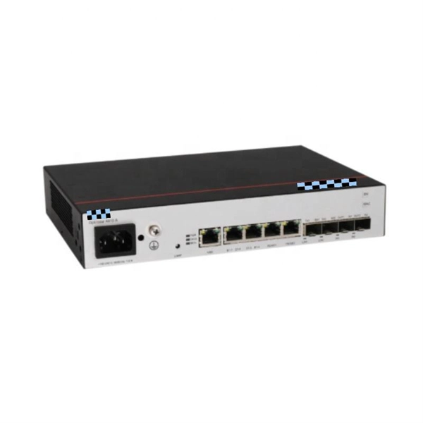
Switches come in three types: those with purely Ethernet ports, those with purely optical ports, and those with a combination of both. Port types are limited to two: optical and Ethernet. Optical ports on switches typically accommodate optical modules for. The optical ports on the switch are usually paired together, with one TX sender and one RX receiver. The. Optical switching represents a fundamental technological evolution, shifting data routing from the domain of electrons to the realm of photons, or light. This transition allows data to remain in its native optical form as it travels through fiber optic networks, eliminating the need for. An all-optical Ethernet switch is a network switch whose service ports are entirely optical, meaning every interface uses fiber rather than copper. This design enables end-to-end optical signal transmission, avoiding the conversion between electrical and optical signals at the switch port level. Copper ports, also known as RJ45 ports, are the most common type of Ethernet switch ports. These ports use twisted-pair copper cables (Cat5e, Cat6, Cat6a, etc. Copper ports are widely used in local area networks (LANs) due to their cost-effectiveness and ease of installation. They can function as core, aggregation, and access devices on campus networks and connect to upstream and downstream devices.
[PDF]

In this blog, we will explore the step-by-step process of using a beamsplitter cube effectively, along with some common applications that benefit from this powerful optical tool. Step-by-Step Guide on Using a Beamsplitter Cube. A beam splitter is an optical device that divides an incoming light beam into two separate beams. One beam is typically reflected while the other is transmitted. The ratio of reflected to transmitted light can vary based on the design of the beam splitter. Beam splitters typically come in the form of a reflective device that can split beams into exactly 50/50, half of the beam being transmitted through the splitter and half being reflected. It is a crucial part of many optical experimental and measurement systems, such as interferometers, also finding widespread application in fibre optic telecommunications. Sometimes it is referred to as a half-silvered mirror. Either way, it is a simple material that YOU could use right at home for cool DIY projects like. The beam splitter has played numerous roles in many aspects of optics. For example, in quantum information the beam splitter plays essential roles in teleportation, bell measure-ments, entanglement and in fundamental studies of the photon. Additionally, beamsplitters can be used in reverse to combine two different beams into a single one. Beamsplitters are often classified according to their construction: cube or plate.
[PDF]

Testing solar panels is easy with a multimeter! To test the current, simply connect the multimeter to the panel's output. Set it to read DC current. A multimeter is an indispensable tool for anyone working with solar panels, allowing for accurate measurements and diagnostics. It empowers users to assess the performance, identify faults, and ensure optimal energy production. Without proper testing and maintenance, solar panels can suffer from. In this article, you will learn the step-by-step process of testing your solar panels using a multimeter. We will cover the essential tools you need, the specific measurements to take, and how to interpret the results. By the end of this guide, you will be equipped with the knowledge to diagnose. With just a simple tool—a multimeter —you can quickly measure your panel's voltage and current. This helps you spot issues early and keep your system running efficiently. Connect the multimeter. 🔋 Learn how to test solar panels using a multimeter — step-by-step! I'll show you how to safely check voltage, amperage, and open-circuit power, so you can confirm if your panels are producing the watts you expect. Perfect for DIY solar builders, RV owners, o. We'll also introduce the Honeytek HK78G 2000V PV Multimeter, a professional tool designed for solar testing. Honeytek, a global.
[PDF]
This article explores the different types of Fiber Optic Sensors, their working principles, and various applications. while constructing a complete Fiber Optic Link (Central Office to Outside Plant to Customer Premise). Hence, this course will. The fiber optic sensor has an optical fiber connected to a light source to allow for detection in tight spaces or where a small profile is beneficial. The optical fiber consists of the core and the cladding, which have different refractive indexes. This is a very interesting and also well-known topic in the research field. Fiber optic sensors play a key role in developing the communication system to sense & measure the change within. Imagine a world where the Internet doesn't just connect but senses —detecting earthquakes, monitoring battery health, or safeguarding critical infrastructure. This is the power of fiber optic sensing, a technology that transforms ordinary optical fibers into the digital world's sensory network. We'll delve into Intrinsic, Extrinsic, and Hybrid fiber optic sensors, explaining how they function. A sensor is a device that measures a physical quantity and converts it into a. Konnexx is an industry leader in Jamaica and the Caribbean, providing world class services in the telecommunication and broadband industries offering a wide range of telecommunication support services for commercial and private entities. We offer comprehensive solution for businesses interested in.
[PDF]

How to Use Optical Power Meter TR-504 | Optical Power Meter Working| Testing OPM, VFL, RJ45 | TRICOM In this video, we walk you through how to use the TRICOM TR-504 Optical Power Meter and explain how it works. Learn how to test fiber optic cables, OPM, VFL . Optical power meters are a key element in the optimization and maintenance of such optical networks and of their components. In this article, learn: What is an optical power meter? An optical power meter (OPM) measures the power levels of light signals in devices that transmit data or power using. An optical power meter measures the strength of light traveling through a fiber optic cable, giving you a reading in dBm (decibels relative to one milliwatt). The basic process is straightforward: turn the meter on, set it to the correct wavelength, clean your connectors, plug in, and read the. OPM interface: insert the fiber to be tested, test the optical power. An optical power meter is a tool that measures the number of optical power in a cable is fiber-optic. It helps engineers verify the performance of optical fiber systems, ensuring that the signal strength meets requirements, and is an essential tool for communication network maintenance and troubleshooting.
[PDF]

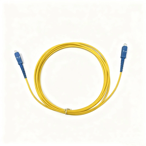
This guide breaks down their technical differences, performance metrics, real-world applications, and how to choose the right one for your network—all optimized for Google SEO and packed with actionable insights. Introduction: Why Fiber Optic Cable Type Matters. Single mode fiber optic cable is made up of a small diameter glass or plastic core surrounded by cladding, which is a layer of reflective material. This small diameter core, typically around 9 microns in diameter, allows only one mode of light to pass through, resulting in a narrower beam of light. But not all fiber cables are created equal: multimode (MM) and single mode (SM) fibers are the two primary types, each engineered for specific use cases, from short-range data center connections to transcontinental telecom backbones. Whether you are an IT specialist, a network manager, or just a curious individual interested in the. As explained by the Fiber Optics Association, fiber optics is the communications medium that sends optical signals down hair-thin strands of extremely pure glass cores. The core is surrounded by the cladding that traps the light in the core. Fiber types are identified by the diameters of the core. The article compares single-mode and multimode fiber optic cables, especially in how their core design, light propagation, and use-cases differ. Core Diameter Single mode fiber: one that has a small light-carrying core that is about 9 micrometers (µm) in diameter.
[PDF]

The LS-SM3101-20C SFP transceivers are high performance, cost effective modules supporting data rate of 125Mbps/155Mbps and 20km transmission distance with SMF. The transceiver consists of three sections: a Cooled EML laser transmitter, a APD photodiode integrated with a trans-impedance preamplifier (TIA). The AFCT-5745NPZ/UPZ Lead-free Singlemode Optical Transceivers have been qualified in accordance to the requirement of Telcordia Document GR-468-CORE under the supervision of Avago Technologies Quality & Reliabil-ity Department. This report summarizes the qualification tests over a range of. Copyright © 2022 GOC-UZ. See our terms of use and privacy policy. Volza's Solution gives you 100x return in Six Months! Use strategic filters to explore Optical transceiver module Import data like a seasoned analyst, uncovering hidden opportunities in the Optical transceiver module import business. Our database includes 321 Import shipments, involving 63 Buyers. Up to now, MEISU has developed various high-temperature resistant optical devices not only with regular SM fiber, but also with PM fiber array by applying special high-temperature coating to the normal PM fiber, providing muiltiple choices for silicon photonic (SiPh) solder reflowable assembly at.
[PDF]
Thank you very much for purchasing Panasonic products. Read this Instruction Manual carefully and thoroughly for the correct and optimum use of this product. Kindly keep this manual in a convenient place fo.
[PDF]
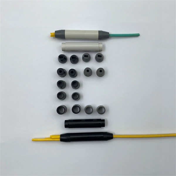
The NanoSpeed™ Series 1×4 solid-state fiber-optic splitter splits the optical power among four outputs with any power splitting ratio. The input is polarization-maintaining (PM) fiber and the outputs are four single mode or PM fibers. Thorlabs offers a wide range of optical beamsplitters. Our plate beamsplitters have a coated front surface that determines the beam splitting ratio while the back surface is wedged and AR coated in order to minimize ghosting and interference effects. Pellicle beamsplitters provide excellent. Beamsplitters are optical components used to split input light into two separate parts. Beamsplitters are also ideal for fluorescence applications, optical interferometry, or life science or semiconductor instrumentation. Light. PLC (Planar Lightwave Circuit) Splitters are designed for single-mode applications and offer an even split ratio from one input fiber to multiple output fibers. Circular beamsplitters, plate beamsplitters and cube beamsplitters can be purchased for polarizing or non polarizing beamsplitting. OZ Optics Online. This is achieved using patent pending non-mechanical.
[PDF]
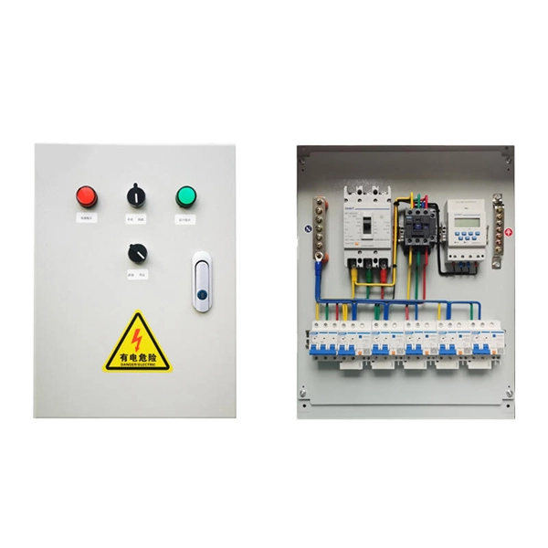
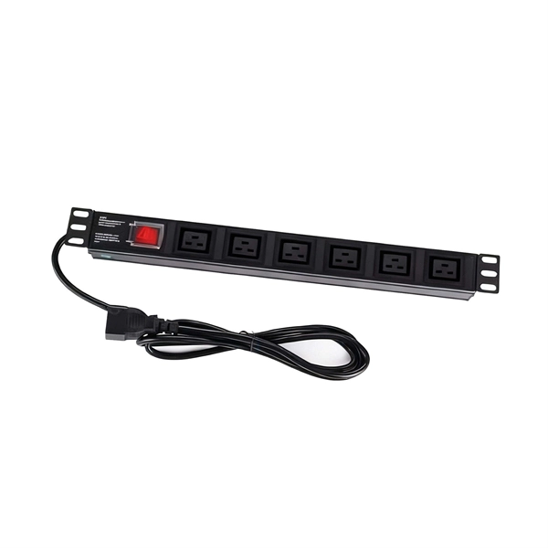
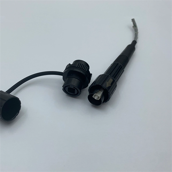
Identify the Pins: Ensure you correctly identify the live (L) and neutral (N) pins. Connect to Power Source: Insert the 2 pin plug into a compatible power outlet. The 2 pin connector is one of the most versatile and simple connectors. It can be used for a variety of different applications. These small, yet powerful components are found in nearly every device--from smartphones to industrial machinery--connecting electrical circuits and ensuring the smooth. A 2-pin DC power connector offers a compact and efficient solution. In this guide, you'll learn exactly what these connectors are, where they're used, and how to choose the best one for your application. It is commonly found in household appliances and electronics. Neutral Pin – Completes the circuit by returning the current. Since there is no earth pin, these plugs are suitable only for devices with double. The cold-pressed wiring of electrical heavy-duty connectors mainly includes the following steps: 1. Prepare tools and materials: You need to prepare cold-pressed terminals, wire strippers, wire crimping pliers, screwdrivers and other tools and materials. I go over all the components and steps to put together a 2 pin Deutsch connection.
[PDF]

BBU end can be connected to CWDM coarse wavelength division multiplexer through CWDM color optical module and OS2 single mode optical fiber patch cord, and then transmitted to CWDM coarse wavelength division multiplexer with one or two optical fibers. The operation of base stations requires a large number of optical modules for interconnection between devices, and we will talk about the application of optical modules in mobile communication base stations. Communication base station is composed of machine room, base station, antenna, feeder. The base station can be divided into two modules: the RRU for transmitting signals and the BBU for processing signals. The BBU is small and exquisite, with low power consumption, while the RRU is large and has high power consumption. In 4G networks, the optical modules used to connect BBU and RRU are mainly gigabit to 10Gbit optical modules. In modern server racks, the wrong optical choice can silently tax performance: queues grow, link training becomes flaky, and operators end up swapping modules mid-quarter. In 5G networks, CPRI is also upgraded to eCPRI. Currently, 5G of the bearer network mainly uses 25Gbps optical.
[PDF]
Learn how to install a fiber optic termination box step-by-step for FTTH projects. Covers mounting, splicing, routing, labeling, and testing for indoor/outdoor use. Installing a fiber optic termination box is one of those jobs that looks simple on paper, but it's. In the realm of optical communication networks, the optical splitter serves a vital role in dividing and distributing optical signals efficiently. Understanding how to properly place and use an optical splitter is essential for optimizing signal quality and ensuring seamless data transmission. WvW Fiber and networking solution. In this video, I walk you through my personal method of prepping and installing a 1:16 fiber optic splitter inside a sealed, weatherproof distribution box getting it ready for field deployment at a site. This is the way I've found to be clean, efficient, and. A fiber optic splitter box is a device used in fiber optic networks to split a single optical signal into multiple signals, allowing for the distribution of data to multiple endpoints. The splitter box contains a splitter, which is a passive optical device that divides the incoming light signal. You use optical couplers and splitters to split or join signals in fiber networks. These devices help you control light signals well. For example, optical splitters send light to many output ports. Have any questions? Talk with us directly using LiveChat.
[PDF]