
In this guide, you will learn how to interpret network diagrams like a pro, from symbols and scope to segmentation, dependencies, troubleshooting, and security clues. A rack elevation diagram is a visual representation of the equipment and components contained within a rack in a data center or server room. It provides a clear overview of the physical layout of the rack, including the placement and positioning of servers, switches, storage devices, and other. Learn how to read and interpret network diagrams effectively to troubleshoot, validate security, and plan network changes with confidence. Have you ever opened a network diagram and felt like you were staring at a subway map with no station names? That is a common problem, even for experienced IT. Network cabinet cabling describes the structured connection and arrangement of all IT components in a server rack. The aim is a secure, maintainable and scalable operation of the network environment. The amount. A standard operating procedure, or SOP, is a set of step-by-step instructions compiled by an organization to help workers carry out complex routine operations. Work instructions should be very detailed on "how" to accomplish a specific job, task or assignment. It helps teams understand network architecture, data flow, and dependencies, making it easier to design infrastructure, troubleshoot issues, and plan.
[PDF]

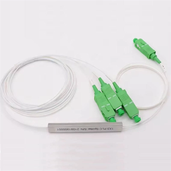
In this case use an optical power meter (OPM) and test the input port of the splitter for the optical power level (dBm) from the OLT at 1490 nm. If there is no or reduced power then the patchcord or OLT is the culprit. If the power level is reduced it could be as simple as a. So for this simple 1X2 splitter, how do we test it? Simply follow the same directions for a double-ended loss test. Attach a launch reference cable to the test source of the proper wavelength (some splitters are wavelength dependent), calibrate the output of the launch cable with the meter to set. Optical splitters in the outside plant (OSP) are used mostly in passive optical networks (PONs) for fiber-to-the-user (FTTx) networks, and are often overlooked as failure points. In this article I focus on a few basics of optical splitters, their applications, typical causes of failures, and how to. Now, we test the simplest 1x2 optical splitter as the picture shown below. 001 dB), OTDR (for reflection event detection). Cleaning tools. The CertiFiber® Pro Optical Loss Test Set (OLTS) can be used to check that the loss of a PON Splitter (often referred to in various standards as a non-wavelength-selective or wavelength-selective branching device) to check that it is within the allowed defined limits. The CertiFiber® Pro has an.
[PDF]

The fastest way to test a fluorescent tube is with a multimeter set to continuity mode. Each end of the tube has two pins connected by a thin filament inside the glass. If either filament is broken, the tube is dead. The whole test takes about 30 seconds per tube once you know what. This is a complete guide for testing a fluorescent light bulb with a multimeter. You don't have to be an expert in electrical work. This process measures electrical resistance to determine if the tube has suffered an internal failure before replacing the bulb or investigating the ballast. This guide provides a comprehensive understanding of the process, equipping you with the knowledge and. To test a fluorescent light bulb, observe any of the following: flickering light, low brightness, buzzing sound, delayed start, and fading color and light variation. Turn off the power to the circuit that powers the fixture and keep the leads steady to ensure accurate readings. Multimeters provide. How to Test Light Bulbs & Fluorescent Tubes with a Multimeter (Continuity Check) Is your lamp or fixture failing to light up? Before you buy a new bulb, you need to confirm if the bulb or tube itself is the problem! A simple continuity check using a multimeter can instantly tell you if the filament.
[PDF]
Fiber testing is the process of verifying the performance of optical fiber cabling. This process includes a range of tests and measurements such as insertion loss, optical return loss, and fiber length. It encompass.
[PDF]

Non-polarizing beamsplitters are specified by their splitting ratio, i. the ratio of P-polarized light to. A beam splitter or beamsplitter is an optical device that splits a beam of light into a transmitted and a reflected beam. It is a crucial part of many optical experimental and measurement systems, such as interferometers, also finding widespread application in fibre optic telecommunications. a laser beam) into two (or sometimes more) beams, which may or may not have the same optical power (radiant flux). Different types of beam splitters exist, as described in the. The collimated incident laser beam passes through the beam splitter, and the output beam is emitted at a specific separation angle on the output beam array. The following figure is an introduction to the basic settings of a beam splitter. Circular beamsplitters, plate beamsplitters and cube beamsplitters can be purchased for polarizing or non polarizing beamsplitting. Beamsplitters are optical components used to split incident light at a designated ratio into two separate beams.
[PDF]
This blog explains how to use Kubernetes resource quotas for efficient resource management. It covers key concepts, step-by-step implementation, YAML examples for Pods, PVCs, ConfigMaps, and tips for monitoring, troubleshooting, and optimizing quotas. On the Quota Management node of the File Server Resource Manager Microsoft ® Management Console (MMC) snap-in, you can perform the following tasks: Create quotas to limit the space allowed for a volume or folder, and generate notifications when the quota limits are approached or exceeded. Generate. Service Quotas is a service for viewing and managing your quotas easily and at scale as your AWS workloads grow. Quotas, also referred to as limits, are the maximum number of resources that you can create in an AWS account. What Are Resource Quotas in. Resource quotas are a tool for administrators to address this concern. A resource quota, defined by a ResourceQuota object, provides constraints that limit aggregate resource consumption per namespace. A ResourceQuota can also limit the quantity of objects that can be created in a namespace by API. Disk quotas allow Windows administrators to control and limit the amount of disk space that users use on the file systems of servers and workstations. Windows Server supports two types of disk quotas: File Server Resource Manager quotas and NTFS quotas.
[PDF]

In this blog, we will explore the step-by-step process of using a beamsplitter cube effectively, along with some common applications that benefit from this powerful optical tool. Step-by-Step Guide on Using a Beamsplitter Cube. A beam splitter is an optical device that divides an incoming light beam into two separate beams. One beam is typically reflected while the other is transmitted. The ratio of reflected to transmitted light can vary based on the design of the beam splitter. Beam splitters typically come in the form of a reflective device that can split beams into exactly 50/50, half of the beam being transmitted through the splitter and half being reflected. It is a crucial part of many optical experimental and measurement systems, such as interferometers, also finding widespread application in fibre optic telecommunications. Sometimes it is referred to as a half-silvered mirror. Either way, it is a simple material that YOU could use right at home for cool DIY projects like. The beam splitter has played numerous roles in many aspects of optics. For example, in quantum information the beam splitter plays essential roles in teleportation, bell measure-ments, entanglement and in fundamental studies of the photon. Additionally, beamsplitters can be used in reverse to combine two different beams into a single one. Beamsplitters are often classified according to their construction: cube or plate.
[PDF]
This guide dives deep into the most prevalent fiber optic network problems, their root causes, and actionable solutions. Fiber optic technology is essential for modern communication, offering unparalleled speed, reliability, and efficiency. However, improper installation can lead to severe performance issues, expensive repairs, and unnecessary downtime. To ensure a high-functioning fiber optic network, avoid these. Understanding the common causes of failure and implementing preventive measures is essential to maintaining reliable networks and avoiding costly downtime. In this article, we explore the primary modes of field failure in fiber optic cables and outline best practices to prevent them. This article outlines three key errors and how to avoid them.
[PDF]

Fiber Optic Welding How To Joint Fiber Optic Cablesplicing fiber optic cable,fiber optic splice,fiber optic,fiber optics,fiber splice,how to splice,fibre opt. The optical fiber connection adopts the fusion splicing method. The whole process is similar to the welding of metal wires, and it is generally carried out by electric isolation. At the moment, there are two methods of connection: Thermal welding of optical fibers consists in bringing the ends of the conductor to melting using a fiber optic splicer, and more specifically - located inside the electrodes. The welded ends are then pressed and a weld is formed. The most work is waiting for installers, whose tasks can be divided into several stages: In this part, we will deal with the second stage, i. welding, which is considered to be one of the most difficult parts of installers' work in. Open the stripping tube and wipe the grease on the optical fiber with toilet paper and alcohol cotton. On the welding disc, make the optical fiber precoil first and cut the optical fiber into an appropriate length to facilitate the coil fiber work after welding. Add heat shrink tube. Procedure. Another method is to use the so-called mechanical welding. It uses special parts that are prepared in advance to connect the two ends. Thanks to this, you can connect two ends of the cable with a ready-made splice, without the need to use an optical fiber splicer. While this method may appear to be.
[PDF]

Learn how to install a distribution box safely and correctly. Covers wiring, placement, standards, and expert tips for a compliant setup. It takes the incoming power and safely distributes it to different. In this video, we'll walk you through the process of wiring a home distribution box with a detailed connection diagram. more Welcome to our channel! In this video. Whether you are an electrical contractor or a construction brigade, knowing how to properly and safely install distribution boxes is the basis of ensuring the safe operation of the entire system. It serves as a central hub for distributing electricity throughout a building, ensuring that power is delivered safely and efficiently to all the required locations. In modern electrical systems, cable distribution boxes (also known as electrical distribution boxes or distribution boxes) play a crucial role as the key hub for managing, distributing, and protecting circuits. Whether it is residential buildings, commercial facilities or industrial sites, the. In this guide, we will break down the key elements involved in connecting the main power supply to your home, providing a clear path for a successful setup. We will focus on the critical parts of the system, from basic components to step-by-step assembly procedures. Whether you are looking to.
[PDF]
Den här guiden går igenom allt du behöver känna till när du vill koppla din egen router till fiber, vilka alternativ som finns, vilka inställningar som krävs och hur du felsöker om något inte fungerar som det ska. However, setting up a fiber optic connection to your router can seem daunting if you're unfamiliar with the process. In this guide, we'll walk you through how to connect a fiber optic cable to a router safely and efficiently. Why Use Fiber Optic Internet? Before diving into the setup, let's quickly. Setting up a fiber internet connection requires understanding key hardware components and following a specific connection sequence to establish your home network. This comprehensive guide combines industry standards with field-tested practices to ensure you achieve a rock-solid.
[PDF]

In this tutorial, I will show you how you can connect the Optocoupler to Arduino, read the data as Analog or Digital, and if necessary convert the analog values to digital, and how to reduce noise from the sensor. The Infrared Slotted Optical Optocoupler Module is a device that uses infrared light to transmit signals between two electrically isolated circuits. It consists of an infrared emitter (LED) and a photodetector (phototransistor) housed in a slotted enclosure. When an object passes through the slot. Slotted Optocouplers (Photo Interrupters) are very useful sensors, often included in Arduino projects to detect position of moving objects, measure speed of rotation, or linear motion, frequency of events, and many others. They are easy to use, but it is important to understand how they work, so. This tutorial is a comprehensive, practical guide to the Speed Sensor / Tacho Sensor (Slot-Type Optocoupler) (Leobot Product #245). Moreover, a simple application is programmed that shows how to wire and how to program an Arduino when working with the module. In this tutorial, the module is used as an “digital input board”. If you want to use the. In this project, I will talk about Phototransistor Optical Interrupter Switches (Opto Coupler) Module, how this module works and helps in determining the speed of a rotating object and finally I will show you how to Interface Optical Interrupter Switch Sensor with Arduino and measure the speed of a.
[PDF]

Excavate the cable at the break point and use a fiber optic cutter to remove the damaged section. Use a high-precision fiber cleaver to prepare the fiber ends for splicing. Step1 : Identify the optical cabinet and network operating center, and find the fiber optic splitter. Step 2: Identify the splitter number. Step 4: Find the optical fiber port and cable sequence that leads to the user. 2) The. Here are the steps to patch a fiber cable. Make sure the connectors are free from dust or dirt and that there is no damage to the cable's. When fiber cables sustain damage, specialized repair techniques help restore connectivity and maintain data integrity. This comprehensive guide outlines professional fiber optic repair protocols that align with industry best practices. Adhering to precise methodologies, we can mend impaired cables. Learn how to splice fiber optic cable step by step in this complete guide! In this video, you'll see the full fiber splicing process — from fiber preparation, cleaving, and fusion splicing to final testing. Whether you're a network technician, IT professional, or telecom operator, you'll find practical steps, tools, and tips to restore. By understanding these key elements and following the outlined steps, you can effectively repair fiber optic cables and maintain the high-performance network necessary for today's demanding communication needs. When it comes to ensuring nice network experiences for users, the condition of a fiber.
[PDF]
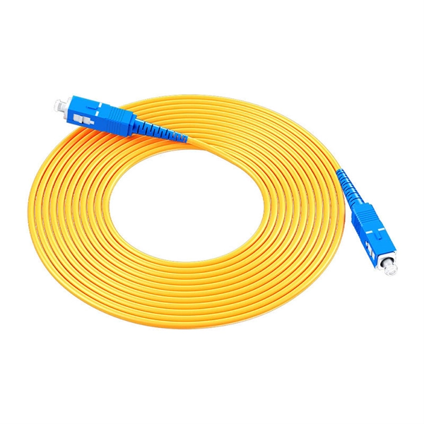
Basic — 1,000 ft single-mode run indoors with minimal termination: Cable $0. 00/ft, Permits $150, Accessories $100. Total ≈ $2,650–$3,100. 60/ft . Free Shipping with $189 Order. 100% Satisfaction Guaranteed. 30-Day Return Warranty Technical Support Live Chat. Pre-terminated Fiber Optic Cable is a hassle-free and reliable solution for realizing fiber connection without huge investment and complicated termination. Simply plug the cable to any. When you buy cables pre-terminated from Discount-Low-Voltage. com, you'll get value pricing and reliable performance. Our pre-terminated fiber optic cables save you the trouble and expense of terminating cables on site, expediting installations and reducing labor costs. 36dB/1000m ² Insertion Loss (1550nm wavelength) for pre-terminated butterfly drop cable with L > 200m: 0. They ensure the efficient delivery of audio, video, data, fiber internet, smart controls, and support HDMI. FS offers pre-terminated multifiber optic cable assemblies at wholesale price that save much installation costs and times for indoor/outdoor fiber optic cabling systems. Buyers typically pay for fiber optic cable by length, fiber type, and installation complexity. This guide presents ranges in USD and practical price estimates to help.
[PDF]

This is a simple video showing how to install a 850nm fiber optic link using SFP transceivers between 2 10 Gigabit backbone switches. Covers transceiver inst. As a leading provider of fiber optic solutions, Weunion offers a wide range of SFP-compatible products, including optical transceivers, DAC/AOC cables, LC patch cords, and MPO/MTP assemblies. This guide explores the essentials of SFP connectivity, installation best practices, and how Weunion's. These transceiver modules are hot-swappable input/output (I/O) devices that plug into 100BASE, 1000BASE and 10GBASE ports (for SFP+), which connect the module port with the fiber-optic or copper network. This document contains these sections: The SFP transceiver modules are hot-pluggable I/O. An optical module is an optoelectronic conversion device that transmits data by converting electrical signals into optical signals. Common types of optical modules include SFP, SFP+, SFP28, QSFP, QSFP28, etc. Different types of optical modules have different performance parameters such as speed. The 1310 nm WWDM solution, 10GBASE-LX4, requires the use of a mode-conditioning patch cord on multimode fiber to achieve its specified range of operating distances. more Audio tracks for some languages were automatically generated. Learn more This is a simple. One of the most widely deployed optical solutions for short-distance 10G links is the multimode SFP+ transceiver, commonly referred to as a 10GBASE-SR module.
[PDF]


