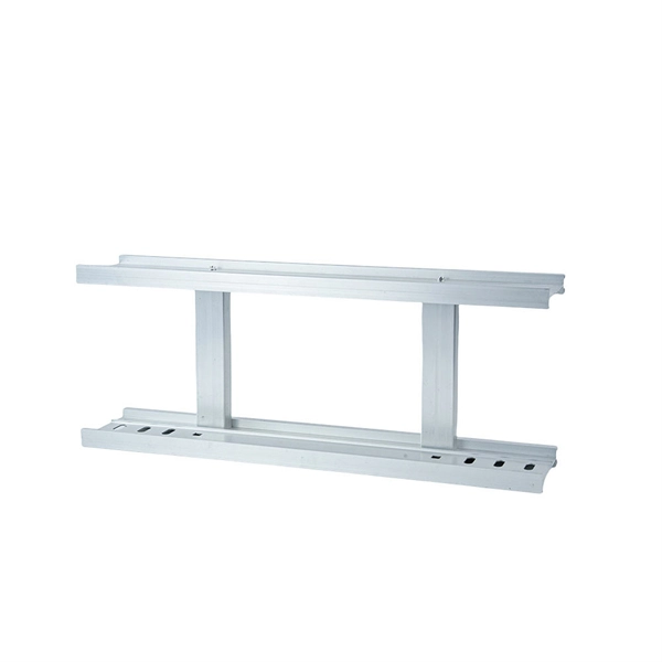
Cable Management Tray Size: Choose a tray size that will hold the desired amount and length of cable. Support Spacing: Remember the NEC requires no more than 4 feet of support spacing. Bend Radius: The tray cable bend radius should be supported to avoid damaging the cable. Hubbell's NEXTFRAME® Ladder Tray is the effective and widely used cable runway that supports and delivers bundles of cable between cabinets, racks, and closets, along walls, and suspended from ceilings. The Ladder Tray features light, rugged, tubular steel construction. It is designed for. maintain spacing or to keep cables in place when the tray is ect the minimum bend ra-dius for cables as they exit the bottom of the cable tray. Proper installation can significantly reduce electromagnetic interference, prevent fire hazards, and improve overall efficiency. This article provides an in-depth. This publication is intended as a practical guide for the proper and safe* installation of cable ladder systems, cable tray systems, channel support systems and associated supports. Cable ladder systems and cable tray systems shall be manufactured in accordance with BS EN 61537, channel support. Is your cable tray system optimized for safety, dependability, space and cost savings? Cable tray (or cable ladder) systems are a popular alternative to electrical conduit systems, as they have an outstanding record for dependable service, design flexibility and cost savings in commercial and.
[PDF]
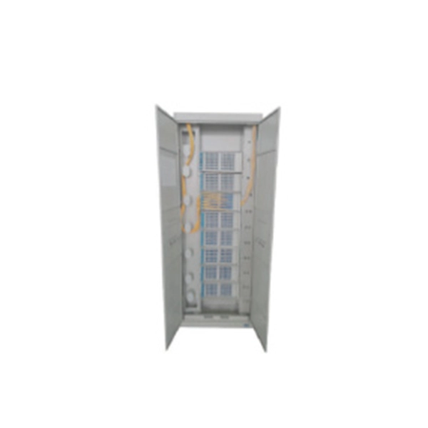
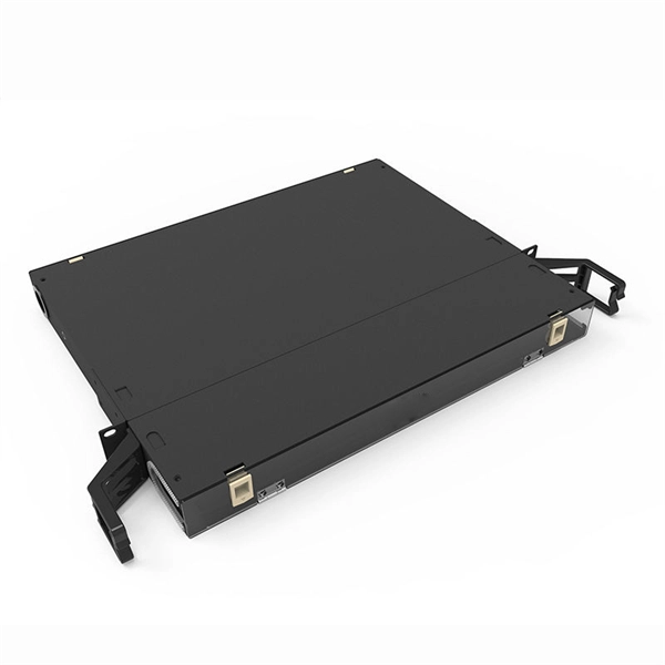
The primary function of a fiber adapter panel is to provide a housing for fiber optic adapters or connectors. These adapters act as the interface between the terminated fiber ends and the active equipment, such as switches, routers, or servers. A fiber patch panel is a mounted enclosure—either rack-mounted or wall-mounted—used to terminate, manage, and interconnect multiple fiber optic cables. It acts as a hub for organizing splices and patch cords, streamlining fiber management and preserving signal integrity. This guide will focus on elucidating the aspects of the fiber patch panel, its accessories, the work done with such a device, and how to. Fiber optic networks are the backbone of fast, reliable internet and modern communications, but even the best fiber cables need the right connectors and patch panels to work efficiently. Connectors are the points where fiber cables link to devices, equipment, or other cables, and using the right. The fiber optic patch panel, also known as the fiber distribution panel, serves as the crucial component of the management of fiber optic cables. Also, the advantage of fiber optic patch panels is to reduce the loss of fiber optic transmission and facilitate engineers to troubleshoot. Serving as the network's centralized junction, it provides secure ports for both incoming and outgoing fibers, streamlining connection.
[PDF]

In this step-by-step guide, we will walk you through the process, ensuring that you can seamlessly connect your optical cable and enjoy a clear and uninterrupted audiovisual experience. Optical cables are becoming increasingly popular for transmitting high-quality. Optical audio cables can easily improve your TV's sound by connecting to external speakers. Learning how to connect an optical cable is easy, but there are a couple of gotchas that you should know. Here are the basics: Identify the optical output; if there's a protective plastic cap, remove it. The most common types are: The Toslink optical cable is a standard for transmitting digital audio signals. It uses a plastic or glass fiber to carry light signals from one. You can connect an older flat screen TV to ANY Stereo system, Surround Sound system, or Soundbar. This video shows you step by step how to make audio connections using an digital optical cable. You can use an optical connection even if your audio system does not have an optical socket, and by using. One of the easiest ways to achieve high-quality sound is to connect your TV to a home theater system or soundbar. Easily connect your optical audio cable to your TV! Follow our step-by-step guide for a hassle-free setup and enjoy crystal-clear sound. No wonder how to improve TV sound, right? When the sound is weak, for example, when using an analog sound source, then an optical audio cable possibly will be the.
[PDF]
If a wire mesh cable tray is supporting cable with a built-in equipment grounding conductor or control or signal cables, then the tray should have a low impedance path to a non-system ground to reduce noise and remove induced or stray currents. Cable tray may be used as the Equipment Grounding Conductor (EGC) in any installation where qualified persons will service the installed cable tray system. There is no restriction as to where the cable tray system is installed. The metal in cable trays may be used as the EGC as per the limitations. Cable tray systems have become an essential component in the infrastructure of modern commercial buildings, smart offices, data centers, and various industrial facilities. These systems provide an efficient and adaptable solution for managing a wide range of cables, including power cables, control. Cable tray grounding wire is the safety connection that links your electrical system's cable tray to the ground. This provides a safe path for any stray electrical currents to flow safely into the earth, avoiding damage to your equipment and reducing the risk of electric shocks. The main purpose of. Do Cable trays have to be grounded? It sounds like a dumb question but if a cable tray has no individual wires in it only raceways, it is not likely to get energized. It involves connecting cable trays to the facility's grounding system, providing a low-impedance path for fault currents and protecting personnel.
[PDF]
This article will focus on the failure rates of optical modules, analyze the primary causes of failure in traditional Digital Signal Processing (DSP) modules, compare failure rates utilizing LPO technology, and discuss the advantages presented by LPO modules. Linear Pluggable Optics (LPO) are a new optical transceiver technology. The idea is simple: instead of a DSP (digital signal processor) inside the module – replacing it with transimpedance amplifier (TIA) and a driver chip with high linearity and EQ capability – LPO shifts signal processing into. Copyright 2023, Coherent. Next-generation 400G and 800G modules for data centers, AI clusters, and telecoms — validated in a European lab, ready to ship from Europe. What is Low-Power Optical Transceivers (LPO)? Linear Pluggable Optics (LPO) replace the DSP inside the optical module with linear analog components, shifting. QSFP-DD LPO TRANSCEIVER DESIGNED FOR PCIE® GEN 5. 0 over optical link, enabling scalable server disaggregation and efficient rack-to-rack interconnects ideal for AI/ML and. Led by Cisco Optics experts, this MSA quickly gained broad industry support due to its vision to create cost-effective solutions for high-density multi-terabit switching, routing, and transport networks. The goal was to define optical specifications that allow for future 100G and 400G pluggable.
[PDF]
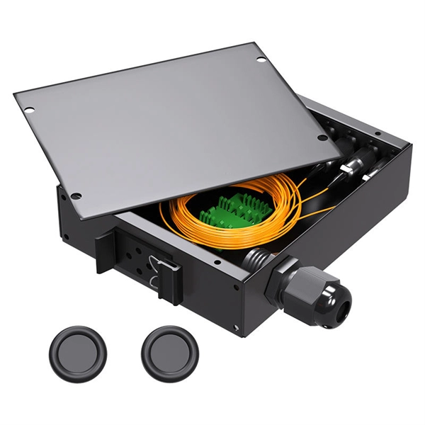
Step-by-step instructions on how to install the Polylok 12" distribution or drainage box. In this guide, we'll break down everything you need to know to install a distribution box correctly and confidently. Choose the right box based on environment (indoor/outdoor), load capacity, and durability. Check for proper IP/NEMA ratings and material quality. Ensure safe placement: install in. The installation of a distribution box is explored in detail, highlighting advanced techniques for achieving a professional and efficient setup. This video provides valuable insights for anyon. more Distribution Box Installation: Advanced Techniques. When it comes to rigid, easy to install electrical box supports, Eaton offers a wide variety of B-Lines series electrical boxes that help reduce installation complexity. For professional installers and property owners, the mechanical components like support rods play a critical role in long-term safety and maintenance efficiency. These components ensure that heavy-duty. Whether you are an electrical contractor or a construction brigade, knowing how to properly and safely install distribution boxes is the basis of ensuring the safe operation of the entire system.
[PDF]
Oglaend System develop, manufacture and sell multidiscipline support solutions, cable ladders, cable trays and accessories such as HVAC, light fittings, tubing clamps, cable cleats, racks and piping. Started back in 1983, Cable House is a recognized name engaged in manufacturing and supplying wide range including Hose Clamps, Cable Ties, Crimping Tools, Cable Tray, Industrial Connectors and more, to the national as well as the international market. With our manufacturing expertise, we have even. With non-slip treaded covers to optimize slip resistance, the BKRS Walkable Cable Tray ensures your cables get the best defense. Chalfant Ladder Cable Tray Systems are ideal for indoor and outdoor cable management. They provide reliability, ease of installation, and cost savings both initially and. Jeetmull Jaichandlall (P) Ltd. is one of the trustworthy Cable Trays Fittings Manufacturers in Zimbabwe that is here to fulfill all your wire mesh and netting tools needs. We believe in building fruitful business partnerships. We offer top-notch Galvanized Cable Trays in Zimbabwe. These metal trays, coated with a special zinc shield, resist rust and last a long time, even in tough environments. They keep your wires tidy, cool, and protected, from. *Check with our Call Centre for latest pricing and availability more. *Check with our.
[PDF]

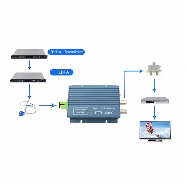
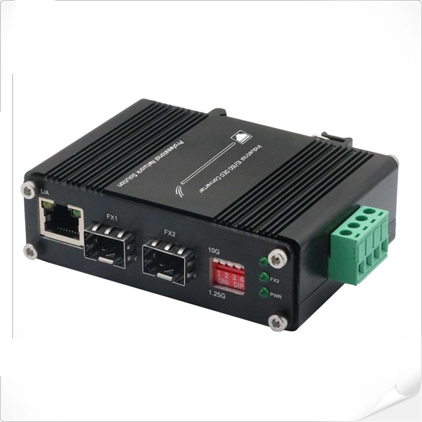
Support Portal provides access to various services for Nokia Customers and Partners, such as Product Documentation, SW Downloads, Ticket Creation and Case Handling. The latest generation of Digital Coherent Optics (DCO) pluggable transceivers represents a breakthrough in the optical networking industry. By combining advances in silicon photonics and Digital Signal Processors (DSP) with Quad Small Form-factor Pluggable – Double Density (QSFP-DD) form factor. Ciena's WaveLogic 6 Extreme 1. 6T quantum-safe encryption solution on the Waveserver platform was designed with this in mind, supporting QKD system interworking and NIST-certified PQC algorithms. It delivers an always-on, wire-speed encryption solution, without impacting performance or adding. 400 Gigabit Ethernet (400G) transceivers are optical modules capable of handling data rates of 400 Gbps. With a transmission rate of up to 400 Gbps, 400G transceivers offer double the capacity of their predecessor (200G transceivers). 400G. ONU, or Optical Network Unit, is a networking device that connects your home or business to the internet using fiber optic cables. It's like a bridge between the vast internet world and your personal network. ONU is a small device that sits somewhere in your house. When you connect your computer. C-Data's ONU products include models that offer data, data + voice, data + CATV, and Triple Play services. They support TR-069 and provide excellent compatibility with third-party OLT systems.
[PDF]
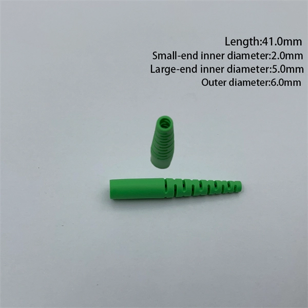
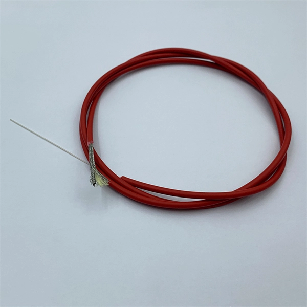
Fast connector is factory pre-polished field-installable connectors that completely eliminate the need for hand polishing in the field. Proven mechanical splice technology ensuring precision fiber alignment, a factory pre-cleaved fiber stub and a proprietary index-matching gel combine. SC/APC Singlemode 0. These fast connectors are compatible with 0. 9 mm tight buffer, 2 mm & 3 mm drop cable. This connector during the installation process does not require. SC UPC Single-Mode Fast Connector featured in pre-polished ferrule and pre-embedded for on-site assembly. It offers convenience in field installation with strong stability. For field assembly installer, the fast connector is small and easy to carry and also can be reused over 5 times.
[PDF]
The Asia-Pacific fiber optic connector in telecom market is analyzed and market size insights and trends are provided by country, product type and cable type as referenced above. The countries covered in the.
[PDF]
To properly remove the optical cable: Locate the port > Stabilize the device > Gently grasp & pull the plug (not the cable) straight out > Do the same with the other end > Cover both connectors with plastic tips. To remove the plastic tip: Gently twist and pull off the protective plastic tip from. The first step in removing an optical cable is to identify which cable you need to remove. This may seem obvious, but it's important to ensure that you are removing the correct cable to avoid any damage or confusion. An optical cable is a type of fiber optic cable that transmits light signals. If your TV is connected to your digital device via an optical cable that needs to be unplugged, and yet you don't know how to remove it, then you are just in the right place. You can easily remove it simply by holding the lock while pulling it towards you. more How to connect soundbar to TV with HDMI and Optical Cable instead of HDMI ARC! Inserting optical cable to your TV or soundbar could be a bit tricky. The process varies depending on the type of connector, but the principle remains the same: unlock, then remove. While specific designs may differ, the general procedure involves a. This guide outlines proper methods to safely remove fiber optic cable from modems in your home or office. As an experienced technology writer who has covered broadband advancements for over a decade, I aim to provide readers with trustworthy instructions endorsed by industry experts.
[PDF]
np is under the management of Ghumti Pasal Pvt. Nepal - Shop for Best Online at Daraz. Great Prices, Even Better Service. For bulk orders or B2B inquiries, email us at Click to Email or call us at +977 9849027214. Prices shown are exclusive of VAT and subject to additional VAT. Have a Bulk Order? AV Jack 2Pin Male Connector-AV1 (Black) online in nepal at Giga Nepal-Electronic components store. Buy loT Robotics parts. Best deals for 2 Pin Connector in Nepal - Pricemandu! Enter your desired price and email. We will notify you when the price reaches your threshold * Shipping prices are only estimates and depend on your location. com With free Home delivery, Cash on delivery and easy return. 13 People watching this product now!.
[PDF]
Mechanical Transfer-Registered Jack (MTRJ) connectors are duplex connectors developed by AMP/Tyco and Corning. They use pins for alignment and come in both male and female guises. It has a plastic bod.
[PDF]

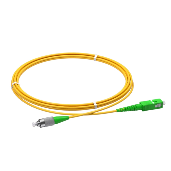
This guide delves into the structure and working principle of fiber optic connectors and outlines the critical steps for creating a successful connection. There are many types of fiber optic connectors, including SC, LC, FC, ST, D4, MU, MT/MPO, etc. These connectors can be divided into single-mode and multi-mode fiber optic connectors according to their structure and purpose. To learn more about the types of fiber optic connectors, click here: Types. Proper connection of fiber optic cables is essential to harness these benefits fully, as even minor errors can lead to significant performance issues like signal loss. This article will guide you through the necessary tools, materials, and methods on how to connect fiber optic cables effectively. At the heart of any robust fiber optic network lies a crucial process: Preparing a fiber cable for termination of a connector or splice. Fiber optic connectors play an essential role in the realm of optical communication, enabling seamless connections between fiber optic cables. We terminate fiber optic cable two ways - with connectors that can mate two fibers to create a temporary joint and/or connect the fiber to a piece of network gear or with splices which create a permanent joint between the two fibers. Whether you are installing a new network or repairing an existing one, ensuring a proper connection is crucial for maintaining optimal signal.
[PDF]
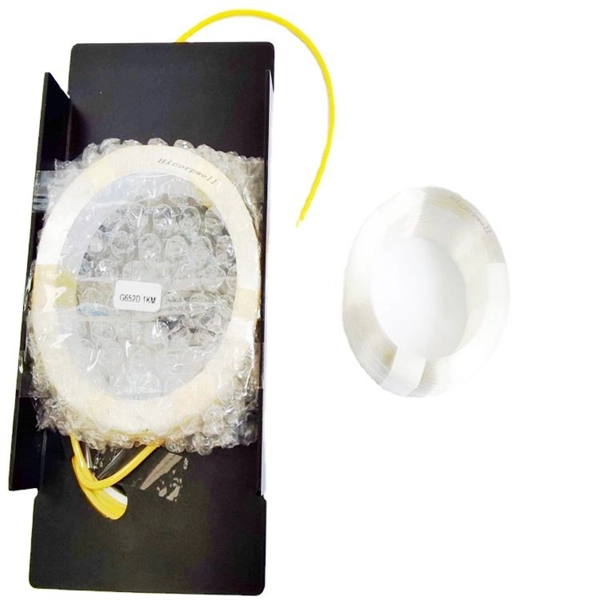
A fiber-optic splitter, also known as a, is based on a of an integrated waveguide power distribution device, similar to a The system uses an optical signal coupled to the branch distribution. The splitter is one of the most important in the link. It is an optical fiber tandem device with many input and output terminals, especially applicable to a passive optical network (,,,.
[PDF]