For systems with fewer than 32 channels, a core switch is generally unnecessary. Basically, the core switch is not required under 50 channels, the second layer switch plus router can be used, and the 100-channel or so will use the efficient routing function of the core switch. First of all, the 100-channel monitoring belongs to a medium-sized network. His network is under. Many engineers also say that I can manage 300 cameras without a core switch, and that's fine! With 10 years of experience as a security R&D engineer, I will tell you how to configure a core switch for cameras. What is a core switch? A network has three layers: access, aggregation, and core. Generally, large enterprise networks and Internet cafes need to buy core switches to achieve robust network scalability to protect the original resources. We will use. Core switches and edge switches are two essential components that play distinct roles in the functioning of a network.
[PDF]

Ensuring Uninterrupted Power Supply: A UPS and DG monitoring system plays a vital role in ensuring uninterrupted power supply. It continuously monitors the power sources, batteries, and overall system performance. A UPS system provides temporary power during electrical outages or disturbances, acting as a bridge until the primary power source is restored or the DG system takes over. They are designed to deliver power instantaneously from energy stored in batteries, super capacitors, or a mechanical storage method. Sensitive electronics, such as computers. UPS or Uninterruptible Power Supply is vital protection against loss of data and costly hardware damage. It ensures that the network systems are operational when the main source of power fails. For home users, a UPS can protect desktop PCs, gaming consoles, and smart home devices from unexpected power cuts. In business settings. These monitoring devices, commonly known as RTUs, will send alerts back to vital personnel via LAN, phone voice message, serial connection, T1, fiber, or other available transport. In this way, organizations can track and log the voltage at the cell level, providing a good assessment of the overall. A 24V DC UPS can manage voltage fluctuations, frequency distortions. These short outages and provide a clean and reliable supply to the control system. With its backup battery pack, a DC UPS designed for an industrial environment will be more resistant to harsh external conditions.
[PDF]
The development of high-performance twisted pair cabling and the popularization of fiber optic cables also drove significant change in the standards. These changes were first released in a revision C in 2009 which has subsequently been replaced by revision D (named ANSI/TIA-568-D).OverviewANSI/TIA-568 is a for cabling for products and services. The title of the standard is Commercial Building Telecommunications Cabling Standard a. ANSI/TIA-568 was developed through the efforts of more than 60 contributing organizations including manufacturers, end-users, and consultants. Work on the standard began with the. ANSI/TIA-568 defines system standards for commercial buildings, and between buildings in campus environments. The bulk of the standards define cabling types, distances, connectors, cable syste.
[PDF]
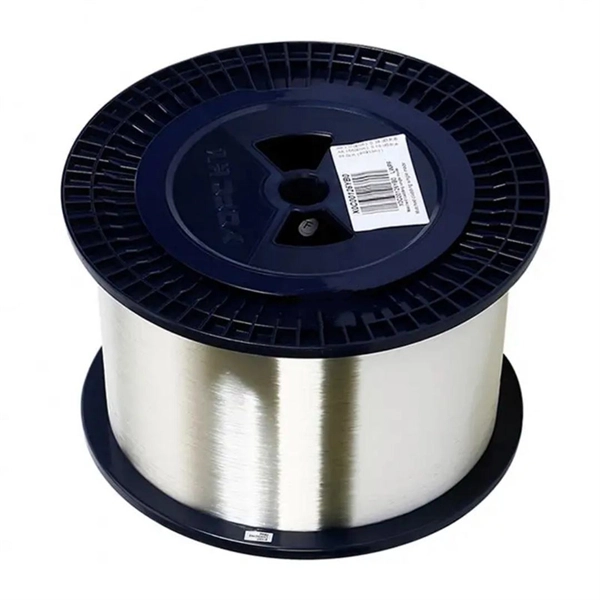
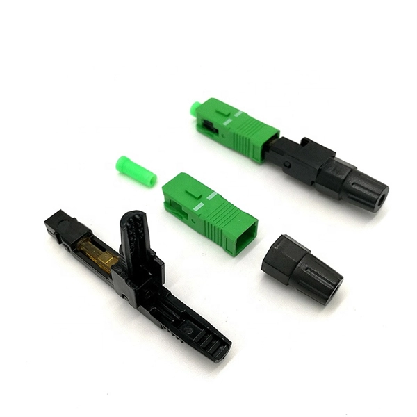
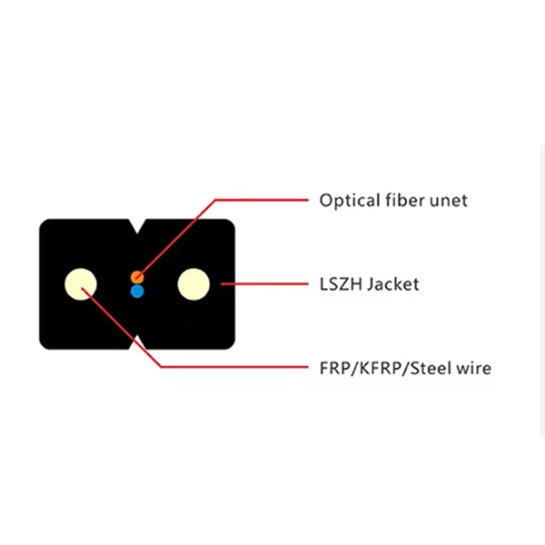
You might have bad connections or lose signal if you bend them too much. Rough handling can also cause problems. Clean them often and manage them with care to stop these issues. If you act early, you will have less downtime. Your network will work better and stay smooth. Proper installation and regular maintenance of fiber optic patch cords play a crucial role in achieving optimized network performance, preventing signal errors, and extending service life. This guide addresses expert-certified best practices applied by professionals in the telecommunications, data. Patching operations must follow principles of neatness, aesthetic cabling, ease of operation, and minimal space usage within ODF frames, optical cross-connects, and integrated boxes. Patch cable lengths should be controlled with a surplus of no more than 500mm. Never use patch cables that are too. Effective fibre optic cable management is crucial for ensuring network reliability, performance, and long-term efficiency. Poorly routed cables, inadequate strain relief, and excessive bending can result in signal loss, increased maintenance, and costly downtime. Incorrect cable lengths can lead to signal attenuation, which refers to the loss of signal strength as it travels through the cable. Plan your fiber patch cord.
[PDF]
Main Source of Lighting for Household by District, Region, and Type of Locality. PxWeb Mark your selections and choose between table on screen and file format. Marking tips Ghana Statistical Services ©2024 | Terms & Conditions. It's helps to drag strangers and robbers from your house when you're away. - 3MP HD Image: The security camera light bulb with 3MP super HD image,let you see the every details. This Lethe battery powered twin security light features a PIR sensor which is a great deterrent for. Dummy security. With over 20 years of experience in the industry, Response has a proven track record of providing high-quality remote monitoring services for our clients. Through the use of advanced technology, we are able to monitor clients' properties 24/7 and receive real-time alerts whenever an alarm is. Buy Remote Home Monitoring Systems Online from Jumia Ghana - Choose from Our Collection of Remote Home Monitoring Systems and Shop them at the best price. Enjoy Cash On Delivery | Secure Payment | Free Returns & more!. 24/7 remote security monitoring and rapid response services. Our experienced team uses the latest techniques and quality materials to. The company offers a comprehensive cloud-based Teleradiology-Platform-As-A-Service (TPaaS) that facilitates secure and efficient management of medical images, making it highly relevant for remote monitoring in healthcare.
[PDF]

Use the SWD or JTAG interface to connect the ST-Link v2 to the STM32 microcontroller. Download and install STM32CubeIDE or another compatible IDE. Install the ST-Link USB driver (available on the STMicroelectronics. The ST-LINK/V2 is an in-circuit debugger/programmer for the STM8 and STM32 microcontrollers. The single wire interface module (SWIM) and the JTAG/serial wire debugging (SWD) interfaces facilitate communication with any STM8 or STM32 microcontroller operating on an application board. ATOLLIC, IAR and KEIL Integrated Development Environments for. How do you use SWD (Serial Wire Debug) for debugging STM32? - HackMD Using SWD (Serial Wire Debug) for debugging STM32 microcontrollers is a powerful way to monitor and control code execution, inspect registers, and analyze faults. Here's a step-by-step guide to set up and use SWD effectively: 1. In addition. This small guide will explain how to connect your debugger to your development board. There are two commonly used connectors which expose only the SWD (Serial Wire Debug) interface or the full JTAG interface. If you are using one of ST's official Nucleo or Discovery boards, you do not have to. To upload a program to a chip from Thomson Semiconductor you need an ST-Link programmer device to connect your PC. Thompson sells branded programmers, adaptors and cables. We'll use an inexpensive ST-LinkV2. They look like AVR programmers but you need to read the pinouts on the side.
[PDF]
Find out the design of robust cable tray installation in pump stations. This manual includes elements such as material choice, cables with heavy loads of the motors, and grounding as a way of providing long-term reliability. This procedure to clear the method of the supply, installations Cable Tray and Trunking System for the project. Delivery and inspection upon arrival of material at site. Installation of the. No description has been added to this video. Enjoy the videos and music you love, upload original content, and share it all with friends, family, and the world on YouTube. Below is the detailed cable tray installation method statement not only for cable tray but also applicable for GI ladder and trunking for indoor and outdoor applications and in service rooms like pump rooms, electrical rooms and plant rooms etc. All materials intended for cable tray, ladder and. Variations of types of armored cables as found by Variable Frequency Drives (VFDs) are much heavier than regular wires. When the tray is too weak, it will bend and may result in dangerous power failure. When electricity is passed through big cables, they become hot. The plastic covering may melt. association representing the major electrical equipment manufac-turers in the U. QA/QC : Quality Assurance / Quality Control Engineer. MIR : Material.
[PDF]
Explore all types of cable trays—ladder, perforated, basket, solid, and channel. Each cable tray type performs a different function and comes in various materials such as aluminum, galvanized steel, and FRP. What is Cable Tray? 1. Non-Metallic What is Cable. Cable tray systems are engineered support structures designed to route, support, and protect insulated electrical cables used for power distribution, control, instrumentation, and communication. Unlike conduit systems, cable trays allow cables to be laid in bundles, improving accessibility, heat. Below are the top 7 types of cable trays and their applications, along with their key advantages. Ladder Type Cable Tray The ladder type cable tray consists of two side rails connected by rungs, allowing excellent airflow around cables. Ladder cable tray is so named because it resembled a ladder. Ladder cable trays are relatively simple in. Selecting the correct cable tray for low voltage system—such as data networking, telecommunications, security, and building automation—is a critical decision that impacts system performance, scalability, and long-term reliability.
[PDF]
This whitepaper describes the various communications technologies while describing the inherent limitations and advantages. Off-grid communication systems, powered by sustainable energy sources like solar, enable vital connectivity in remote locations, during emergencies, and for operations requiring autonomous communication capabilities. From remote European mountain refuges to industrial facilities operating in. Introduction: Free Space Optics (FSO) is a wireless optical technology that transmits data via laser beams. It leverages light waves to transmit and receive data in a Line-of-Sight (LOS) path between buildings. Unlike Optical Fiber Cable (OFC), FSO uses air as the medium for data transportation. Solar powered communication systems, harnessing the sun's energy to power various communication devices and networks, represent a significant step towards achieving this goal. This essay will explore the diverse applications, benefits, challenges, and future prospects of these systems. This paper aims to explore the FSO system, analyze previous research, and discuss the challenges associated. Solar light communication is a technology that utilizes light emitted from solar-powered sources to transmit information. Employs modulation techniques to encode data within light signals, 3. Low Noise Amplifiers (LNAs) are a key component in many electronic systems and communication devices. These critical elements are used extensively to amplify.
[PDF]

Cable trays play a key part in keeping fire protection systems working. Here is what they do: They Make Safe Paths for Fire System Wires Cable trays are made from materials that resist fire. They can help stop fire from spreading. Recognize electrical cable tray misuse that can lead to electric shock and arc-flash/blast events and fires caused by overheating. The use and installation of cable trays is covered by legally enforceable OSHA regulations in 29 CFR 1910. 305(a)(3), or comparable standards promulgated by States. Scope: Firestopping for busway, cable trays, cables, and trunking passing through walls in enclosed electrical installations. Where cables pass through shafts, walls, slabs, or enter electrical panels or cabinets, openings shall be tightly sealed with firestopping materials in accordance with. Cable trays can be part of a planned cable management system to support, route, protect, and provide a pathway for cable systems. Power, low voltage control, data, or telecommunications wiring distribution systems can be used with cable trays. 1 This section applies to cable trays utilized to support and route low voltage cables (telecom, security, A/V). No fire alarm cables will be permitted to be installed in cable trays. If a fire starts, the tray protects the wires inside from flames and.
[PDF]
Ensure safe placement: install in dry, accessible areas with good ventilation and at appropriate height (typically ~1. Practice good wiring: secure grounding, neat cable management, proper insulation, and correct wire gauge and breaker size. Include protection devices like breakers, fuses, and. Whether you are an electrical contractor or a construction brigade, knowing how to properly and safely install distribution boxes is the basis of ensuring the safe operation of the entire system. This article details the process of installing them, which helps you comprehend distribution boxes. Electrical systems power our homes, offices, and industrial facilities, but behind every reliable electrical setup lies a crucial component that often goes unnoticed: the distribution box. This essential piece of equipment serves as the nerve center of your electrical system, managing power flow. It also follows building rules. Use more than one SPD for stronger protection. Many SPDs help guard your building from surges. Just like travelers need clear pathways and safety protocols, your electrical circuits need proper management to prevent chaos. Whether it is residential buildings, commercial facilities or industrial sites, the.
[PDF]
The PL-1000D simultaneously monitors up to 16 fiber strands, eight on the OTDR and eight on the OSA, and operates standalone over dark fiber, lighted fiber, or a third party network without impacting network traffic. The device monitors the entire D. The PL-1000D simultaneously monitors up to 16 fiber strands, eight on the OTDR and eight on the OSA, and operates standalone over dark fiber, lighted fiber, or a third party network without impacting network traffic. The device monitors the entire DWDM C-band spectrum and provides the optical spectrum, OSNR, and OTDR measurements of the fiber. The OTDR locates fiber cut by sending high powered optical pulses into the fiber and creating Rayleigh back-reflections. The returning signals are measured and calculated, indicating the accurate location and intensity of the fault. The OTDR supports GIS (Geographic Information System) using Rest API, enabling precise geographic location of disrupt. The OSA enables the user to monitor the OSNR and optical spectrum of each fiber and shows a full, accurate and detailed picture of the wavelengths used in the fiber. OSADiagram Graphical Display of the OSA, from PacketLight's LightWatch NMS Please contact usfor a quote or further assistance.
[PDF]
This system enables tracking of the presence and relative intensity of multiple wavelength-division-multiplexed (WDM) data streams that span over a broad frequency band with high resolution, accuracy, and fast measurement update rates. In fiber-optic communications, wavelength-division multiplexing (WDM) is a technology which multiplexes a number of optical carrier signals onto a single optical fiber by using different wavelengths (i., colors) of laser light. This allows multiple channels of data to be transmitted simultaneously. Typically ships in 21 day (s) Actual lead time confirmed upon receipt of order. EDGE HD-DWDM modules incorporate LC APC connections on single fiber ports and MDC APC connections on two-fiber output channel pairs. 6i, 12i and 24i modules are used for the initial channels deployed, while 12u and 24u. Wavelength Division Multiplexing increases fiber capacity by combining (mux) and separating (demux) multiple input channels over a single fiber output. This guide delves into the principles, types, applications, and future trends of WDM. Tailored for professionals sourcing solutions from CommMesh, it. We propose a novel (to our knowledge) and simple real-time optical monitoring (RTOM) system for dynamic spectral analysis of telecommunication signals, involving electro-optic (EO) temporal sampling followed by dispersion-induced frequency-to-time mapping and high-speed photodetection.
[PDF]
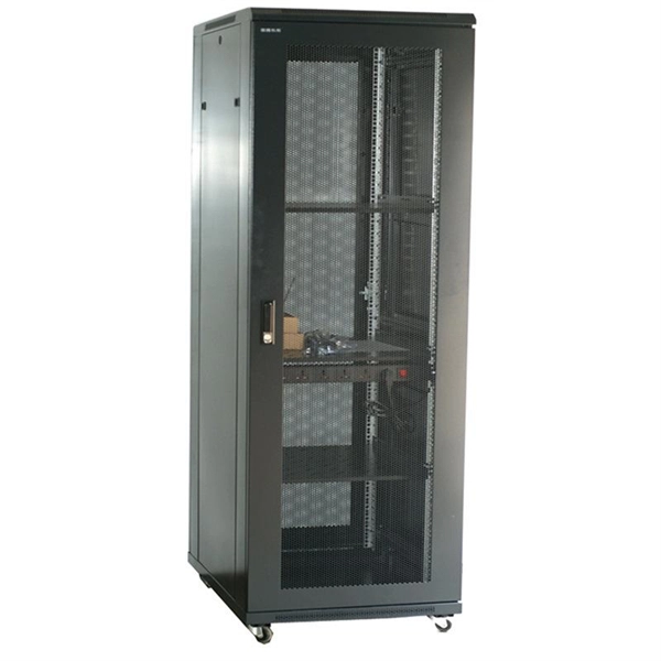
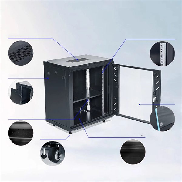
So as we move along answering the question of “What does 1U mean?” let's move on to who came up with this stuff in the first place! Rack Units were created by the Electronic Industries Alliance (“EIA”) to help standardize equipment use. So as we move along answering the question of “What does 1U mean?” let's move on to who came up with this stuff in the first place! Rack Units were created by the Electronic Industries Alliance (“EIA”) to help standardize equipment used my telecommunications carriers. The specification is known as EIA-310. Although rack units got a birth in telecom. A “U” or rack unitis a measurement of the height of a piece of computer or network gear that is designed to fit into a standard 19″ or 23″ rack. A single rack unit is exactly 1.75″ (44.45 MM) in height, although many manufacturers will make their equipment slightly smaller than this to ease installation into racks where things were not spaced as ac. On most modern racks, the rack units will be visibly labeled with numbers and lines (generally white on black racks; black on beige racks). These lines indicate where the top and bottom of the rack unit starts. the number is generally in the center of the rack unit. Older racks without silk-screened numbers and lines are usually denoted by a small. EIA-310 also sets the specifications for the hole spacing, both vertically and horizontally of rack units within racks and cabinets.
[PDF]
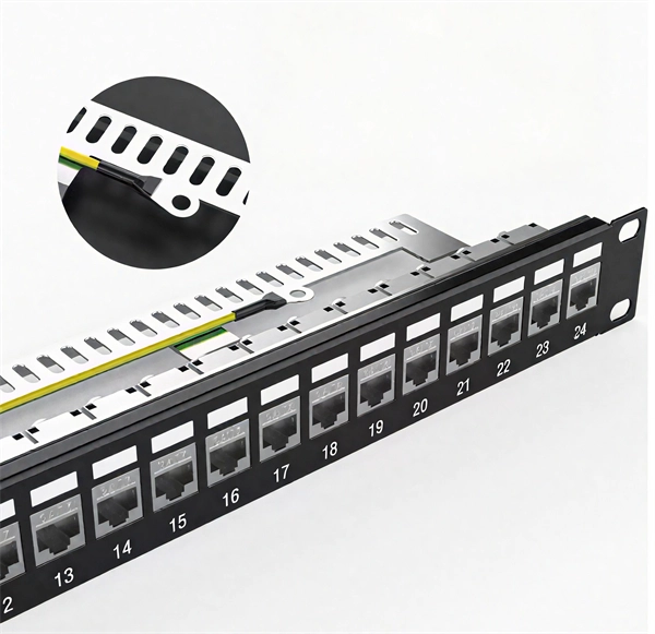
Standards IEC 30129 and AS 30129 Telecommunications Bonding Networks for Buildings and Other Structures and Standard TIA607-E Generic Telecommunications Bonding and Grounding (Earthing) for Customer Premises provide guidance on the design and installation of the indoor grounding . Standards IEC 30129 and AS 30129 Telecommunications Bonding Networks for Buildings and Other Structures and Standard TIA607-E Generic Telecommunications Bonding and Grounding (Earthing) for Customer Premises provide guidance on the design and installation of the indoor grounding . Below is a comprehensive guide for implementing effective bonding and grounding systems in data centers. The Mesh-BN is the backbone of the bonding system, designed to ensure a uniform electrical potential across the entire data center. The whole structure consists of a metal circuit, a protect bus, and a ground wire. Network hardware is connected to PDUs and constantly. ed grounding kits shall be UL Listed, CSA Certified and RoHS compliant. Grounding strip and connectors shall be tin-plated. Grounding strip shall comply with EIA niversal mounting hole spacing and mount to standard racks and cabinets. The offering is designed with products that installers can use to make BICSI and ANSI/TIA/EIA-607 compliant installations.
[PDF]