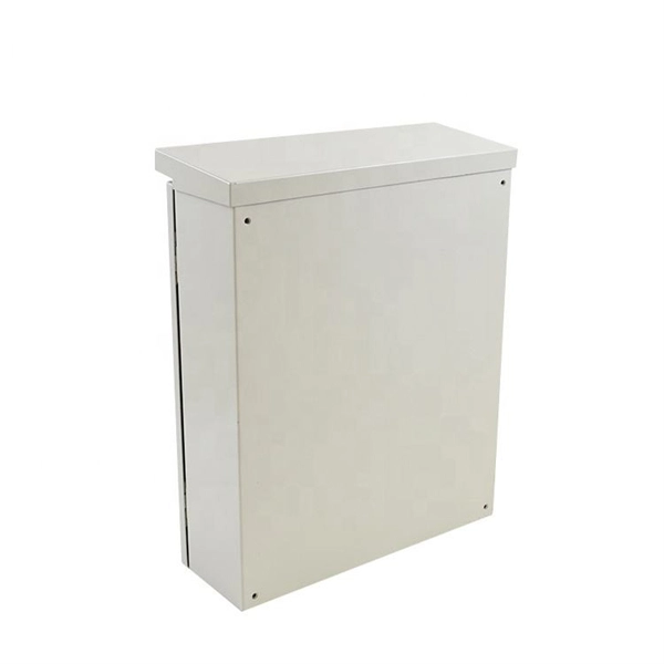
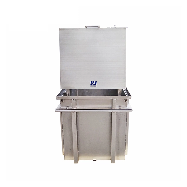
In this video, we unbox the MO01 Market Terminal and take a first look at what's inside the box and how it fits into a modern desk setup. MO01 is not a mining rig. It's a compact, always-on desktop market terminal designed to keep real-time information within reach—quietly and. We walk you through what comes in your Payanywhere Smart Terminal box. For more information visit: https://www. com Our customer support team is available to help 24/7. Enterprise members also receive dedicated account managers and a guaranteed uptime SLA. All. Our Terminal Box provides a safe, reliable, and convenient way to perform online partial discharge (PD) measurements as well as online temporary and permanent PD monitoring on rotating electrical machines, power cable joints and terminations, and other assets. It connects OMICRON PD measurement and. The Cerbo GX is a powerful member of the GX product family, an advanced communication centre that monitors and controls energy systems. MO01 is not a. This is "Unboxing the Helcim Smart Terminal (in 1 minute)" by Helcim on Vimeo, the home for high quality videos and the people who love them. How can we improve? Choose from our selection of terminal boxes, including over 4,300 products in a wide range of styles and sizes. Same and Next Day Delivery.
[PDF]

Use the SWD or JTAG interface to connect the ST-Link v2 to the STM32 microcontroller. Download and install STM32CubeIDE or another compatible IDE. Install the ST-Link USB driver (available on the STMicroelectronics. The ST-LINK/V2 is an in-circuit debugger/programmer for the STM8 and STM32 microcontrollers. The single wire interface module (SWIM) and the JTAG/serial wire debugging (SWD) interfaces facilitate communication with any STM8 or STM32 microcontroller operating on an application board. ATOLLIC, IAR and KEIL Integrated Development Environments for. How do you use SWD (Serial Wire Debug) for debugging STM32? - HackMD Using SWD (Serial Wire Debug) for debugging STM32 microcontrollers is a powerful way to monitor and control code execution, inspect registers, and analyze faults. Here's a step-by-step guide to set up and use SWD effectively: 1. In addition. This small guide will explain how to connect your debugger to your development board. There are two commonly used connectors which expose only the SWD (Serial Wire Debug) interface or the full JTAG interface. If you are using one of ST's official Nucleo or Discovery boards, you do not have to. To upload a program to a chip from Thomson Semiconductor you need an ST-Link programmer device to connect your PC. Thompson sells branded programmers, adaptors and cables. We'll use an inexpensive ST-LinkV2. They look like AVR programmers but you need to read the pinouts on the side.
[PDF]
For systems with fewer than 32 channels, a core switch is generally unnecessary. Basically, the core switch is not required under 50 channels, the second layer switch plus router can be used, and the 100-channel or so will use the efficient routing function of the core switch. First of all, the 100-channel monitoring belongs to a medium-sized network. His network is under. Many engineers also say that I can manage 300 cameras without a core switch, and that's fine! With 10 years of experience as a security R&D engineer, I will tell you how to configure a core switch for cameras. What is a core switch? A network has three layers: access, aggregation, and core. Generally, large enterprise networks and Internet cafes need to buy core switches to achieve robust network scalability to protect the original resources. We will use. Core switches and edge switches are two essential components that play distinct roles in the functioning of a network.
[PDF]
Encuentra y compara las mejores soluciones de Rack y Gabinetes de Servidores en Colombia. Selecciona la opción que mejor se ajuste a tus necesidades y solicita cotización al proveedor. Internet providers in Colombia are evolving rapidly, offering faster speeds, wider coverage, and competitive pricing across the country. Whether you're in a major city or a growing town, finding the right ISP can transform how you work, stream, and stay connected. This guide explores the top. CoreSite Colocation Services is a service that provides scalable data center solutions designed to facilitate secure and reliable housing of IT infrastructure. The service offers space, power, cooling, and physical security for servers and network equipment, enabling businesses to optimize their.
[PDF]
The PL-1000D simultaneously monitors up to 16 fiber strands, eight on the OTDR and eight on the OSA, and operates standalone over dark fiber, lighted fiber, or a third party network without impacting network traffic. The device monitors the entire D. The PL-1000D simultaneously monitors up to 16 fiber strands, eight on the OTDR and eight on the OSA, and operates standalone over dark fiber, lighted fiber, or a third party network without impacting network traffic. The device monitors the entire DWDM C-band spectrum and provides the optical spectrum, OSNR, and OTDR measurements of the fiber. The OTDR locates fiber cut by sending high powered optical pulses into the fiber and creating Rayleigh back-reflections. The returning signals are measured and calculated, indicating the accurate location and intensity of the fault. The OTDR supports GIS (Geographic Information System) using Rest API, enabling precise geographic location of disrupt. The OSA enables the user to monitor the OSNR and optical spectrum of each fiber and shows a full, accurate and detailed picture of the wavelengths used in the fiber. OSADiagram Graphical Display of the OSA, from PacketLight's LightWatch NMS Please contact usfor a quote or further assistance.
[PDF]
Epson Device Admin is an application that allows you to install devices on the network, and then configure and manage the devices. The following outlines the main features. A complete multi-vendor reference for GPON/EPON OLT configuration, monitoring & troubleshooting. This repository serves as a technical knowledge hub for network engineers working with FTTH (GPON/EPON) infrastructure. It contains configuration commands, troubleshooting methods, power-check commands. Streamline configuration and management for your Epson printer fleet. With automatic device discovery, this intuitive software helps save. OpManager monitors ZTE-ZXPON-EPON-ONU for health and performance. With the help of our ZTE-ZXPON-EPON-ONU device template, you can easily discover and monitor critical performance metrics without any hassle. This guide dives deep into EPON technology, its benefits over alternatives like GPON, and the critical role of optical modules. Whether you're a network engineer or a tech. This document provides examples of configuring Ethernet Passive Optical Network (EPON). The configuration examples in this document were created and verified in a lab environment, and all the devices. Versatile dual-layer tester purpose-built for PON service activation, with added broadband capabilities. The PPM1 leverages a unique patented technology that makes all the difference in the field.
[PDF]

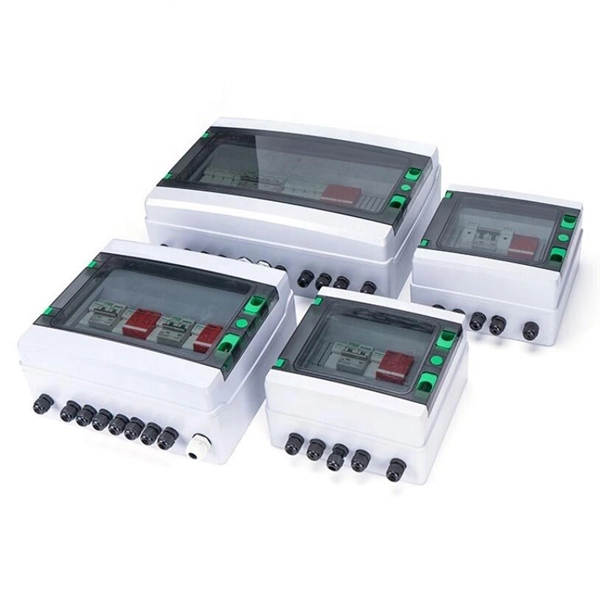
Also, please take a look at the list of 17 ac distribution box manufacturers and their company rankings. Rockwell Automation, 2. Xiamen Panelroof PV Technology Co. We have been designated as a listed company equipment manufacturer for multiple enterprises. Product Details: Custom Power Distribution Box from J&HW Group, designed for various applications with a focus on cost efficiency and customization. Product Details: GEYA is a power distribution box manufacturer with characteristics that include a maximum voltage of 600 VAC, main circuit breaker. The top distribution box manufacturers in 2025 are SENTOP, Schneider Electric, Rockwell Automation, Hammond Manufacturing, Laiwo Electrical, J&HW Group, Siemens, ABB, Eaton, Legrand, and General Electric. These companies make rules for safety and performance. It is important to pick a reliable. As urbanization accelerates and green energy transforms our grids, the companies producing these critical electrical systems are scaling up like never before. Global demand for electrical equipment is projected to grow by 18% annually through 2025, driven by smart city developments and renewable. Global Leaders: Major corporations like Schneider Electric, ABB, Siemens, Eaton, and Legrand dominate the market with extensive product portfolios, advanced technologies, and strong global distribution networks. Grandviewresearch Olayksele Regional & Specialized Manufacturers: A significant number.
[PDF]
PoE switches (Type 1) comply with the IEEE 802. 3af standard, which specifies the maximum power delivered over Ethernet cables. 4 watts of power per port, while PDs can consume up to 12. UPoE supports higher-powered devices, including advanced Wi-Fi 6 APs, video conferencing endpoints, large-screen digital signage, and compact desktop switches. The latest IEEE standard (802. 3bt), supporting up to 90 W per port. UPoE+ can power advanced devices like LED lighting systems. Power over Ethernet (PoE) is a widely used LAN technology that provides DC power to endpoints over existing copper Ethernet cabling used for data connectivity. This eliminates the need for separate power supplies for devices such as IP cameras, VoIP phones, or wireless access points.
[PDF]
This system enables tracking of the presence and relative intensity of multiple wavelength-division-multiplexed (WDM) data streams that span over a broad frequency band with high resolution, accuracy, and fast measurement update rates. In fiber-optic communications, wavelength-division multiplexing (WDM) is a technology which multiplexes a number of optical carrier signals onto a single optical fiber by using different wavelengths (i., colors) of laser light. This allows multiple channels of data to be transmitted simultaneously. Typically ships in 21 day (s) Actual lead time confirmed upon receipt of order. EDGE HD-DWDM modules incorporate LC APC connections on single fiber ports and MDC APC connections on two-fiber output channel pairs. 6i, 12i and 24i modules are used for the initial channels deployed, while 12u and 24u. Wavelength Division Multiplexing increases fiber capacity by combining (mux) and separating (demux) multiple input channels over a single fiber output. This guide delves into the principles, types, applications, and future trends of WDM. Tailored for professionals sourcing solutions from CommMesh, it. We propose a novel (to our knowledge) and simple real-time optical monitoring (RTOM) system for dynamic spectral analysis of telecommunication signals, involving electro-optic (EO) temporal sampling followed by dispersion-induced frequency-to-time mapping and high-speed photodetection.
[PDF]
Pilot-wire relaying is an adaptation of the principle of differential relaying to line protection and functions to provide high-speed clearing of the line for faults anywhere on the line. Pilots include wire pilot (us.
[PDF]
Wiring a CCTV Camera to Power Supply Box with Premade Siamese CableThis video shows installers how to connect a CCTV camera to a 12V DC power supply box using premade Siamese security camera cables. The process is e. Wiring a CCTV Camera to Power Supply Box with Premade Siamese CableThis video shows installers how to connect a CCTV camera to a 12V DC power supply box using premade Siamese security camera cables. The process is exactly the same for 24VAC power supply boxes, except that the cable polarity does not matter with alternating current (+ and - does not matter with 24VAC wiring). Our latest model power supply boxes use PTC auto reset fuses instead of traditional one time use fuses. The above image shows a power supply box on the left that uses traditional fuses. The one on the right is our latest generation model, which uses PTC. PTC is much more convenient because when there is a short circuit, the PTC turns the circuit of. Below are some examples of how multi-channel power supply boxes can be installed with analog CCTV cameras, HD security cameras, and audio surveillance microphones. We have the following complete how-to guides available. Please use the below links to access complete guides. 1. Security Camera Installation Using RG59 Siamese Coax Cable Spools 2. Secu. Here are the most common ways that power supply boxes are used in video and audio surveillance installations. Please access the detailed guides using the above links.
[PDF]
So as we move along answering the question of “What does 1U mean?” let's move on to who came up with this stuff in the first place! Rack Units were created by the Electronic Industries Alliance (“EIA”) to help standardize equipment use. So as we move along answering the question of “What does 1U mean?” let's move on to who came up with this stuff in the first place! Rack Units were created by the Electronic Industries Alliance (“EIA”) to help standardize equipment used my telecommunications carriers. The specification is known as EIA-310. Although rack units got a birth in telecom. A “U” or rack unitis a measurement of the height of a piece of computer or network gear that is designed to fit into a standard 19″ or 23″ rack. A single rack unit is exactly 1.75″ (44.45 MM) in height, although many manufacturers will make their equipment slightly smaller than this to ease installation into racks where things were not spaced as ac. On most modern racks, the rack units will be visibly labeled with numbers and lines (generally white on black racks; black on beige racks). These lines indicate where the top and bottom of the rack unit starts. the number is generally in the center of the rack unit. Older racks without silk-screened numbers and lines are usually denoted by a small. EIA-310 also sets the specifications for the hole spacing, both vertically and horizontally of rack units within racks and cabinets.
[PDF]
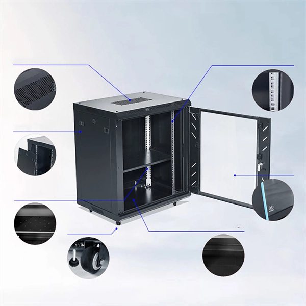
In this blog, we'll walk through the standard procedures for installing racks and assembling MPO systems in modern data centers. Before any hardware is installed, detailed planning is essential. Rack placement must consider airflow, power distribution, cable routing, and physical. Proper installation of components in a data center server rack is crucial for optimal performance, efficient maintenance, and long-term reliability of your IT infrastructure. The term breaks down into two distinct phases: “racking” involves assembling and mounting servers, switches, storage devices, and networking equipment into. Best Practices for Data Center Rack and Stack Installation in 2025. Data centers are the backbone of modern technology, and ensuring their infrastructure is installed correctly can significantly impact performance and scalability. Data. However, before you get down to installation itself, it's necessary to prepare for it. A preparatory stage includes several important pre-installation steps that ensure smooth and durable functioning. These include: Choosing the right rack type. Server furniture differs a lot. Modern manufacturers. Four-Post Racks To mount two-post racks, the equipment has to be bolted to two vertical posts, in most cases at the front. They are simple, cheaper than other types, and occupy less space. They are a good choice for small IT rooms or closets with minimal depth requirements and lightweight devices.
[PDF]
This guide provides instruction on how to install and configure your MS130R series switch. For more switch installation guides, refer to the switch installation guides section on. This guide provides step-by-step instructions for installing two common types of industrial switches: rack-mount, and DIN-rail switches. Choose the Installation Location: Select an appropriate spot on the DIN rail for mounting. This chapter describes how to start your switch and how to interpret the power-on self-test (POST) that ensures proper operation. No prior experience needed—just follow along and you'll have your switch installed and running in minutes. more In this video you'll see a complete, step-by-step guide to mounting. This typeface indicates command syntax, or represents information as it is displayed on the screen. When you see the word enter in this guide, you must type something, and then press the Return or Enter key. Do not press the Return or Enter key when an instruction simply says type. Here, we explore the four most common installation methods for industrial switches: Desktop installation is the most straightforward approach— placing the switch like a small box directly on a table, control panel surface, or equipment rack without extra fixtures. Simple setup: No tools required.
[PDF]
The cabinet or rack must also meet the following requirements: The minimum vertical rack space per chassis should be 1 RU, equal to 1. The width between the inside edges of the mounting posts must be at least 17. See Reference Perforated Cabinet. Standard two-post telco rack, with mounting posts. Russia Data Center Rack Market by Rack Size (Quarter Rack, Half Rack, Full Rack), by End-User (IT & Telecommunication, BFSI, Government, Media & Entertainment, Other End-Users), by Russia Forecast 2026-2034 As requested- presale engagement was good, your perseverance, support and prompt responses. Certified Design, Facility and Operations by Uptime Institute. PCI DSS and ISO compliant. Bandwidth over 100 Gbit/s. Round-the-clock access. Hardware mount/dismount, troubleshooting and delivery to data center. If you need an. Russia data center rack market size in 2026 is estimated at USD 290. 23 million, growing from 2025 value of USD 253. 47% CAGR over 2026-2031. 3 cm) (two- or four-post EIA cabinet or rack, with mounting rails that conform to English universal hole spacing per section 1 of ANSI/EIA-310-D-1992). For more information, see Requirements Specific to Perforated. A data center rack is a standardized frame that houses servers, storage systems, networking equipment and other computing hardware in a secure, organized environment. These racks are designed to provide efficient cooling, cable management and power distribution in data centers, ensuring peak.
[PDF]