Market Size by Fiber Type, by Deployment, by Cable Type, by End Use Industry – Global Forecast. The global fiber optic cable market was valued at USD 13 billion in 2024 and is estimated to grow at a CAGR of 10. The Fiber Optic Cable Market Report is Segmented by Cable Type (Armored Cable, Non-Armored Cable, and More), Fiber Mode (Single-Mode Fiber, Multi-Mode Fiber, and More), Installation Type (Aerial/Overhead, Underground/Buried, and More), End-User Industry (Telecommunication, Power Utilities and Smart. The global Fiber Optic Cable Market is anticipated to be worth USD 5. It is expected to grow steadily and reach USD 11. This growth represents a CAGR of 7. 21% during the forecast period from 2026 to 2035. I need the full data tables, segment breakdown, and. The fiber optics industry is projected to reach USD 6. 8 billion by 2029 from USD 3. Rapid expansion of data centers, cloud services, and 5G infrastructure is driving strong adoption of fiber optic solutions. 64% between 2023 and 2028. The market is experiencing significant growth, driven by the increasing demand for high-speed internet connectivity and the expansion of data centers.
[PDF]
In 1880, and his assistant created a very early precursor to fiber-optic communications, the, at Bell's newly established in. Bell considered it his most important invention. The device allowed for the of sound on a beam of light. On June 3, 1880, Bell conducted the world's first wireless transmission between two buildings, some 213 meters apart. Due to its use of an atmospher.
[PDF]

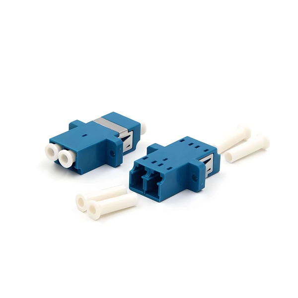
Fusion splicing is the most widely used method of splicing as it provides for the lowest loss and least reflectance, as well as providing the strongest and most reliable joint between two fibers. Virtually all singlemode splices are fusion. There are two main methods of splicing: mechanical splicing and fusion splicing. This blog will delve into the nuances of each method, comparing their costs, labor efficiency, network performance, and more, to help you decide which splicing technique is best suited for your needs. Why splice? Fiber. Fusion splicing is the process of fusing or welding two fibers together usually by an electric arc. Fiber splicing means joining two optical fibers (permanently or temporarily) such that light guided in one fiber and reaching the joint (splice) can be transferred into the second fiber with low insertion loss. Another method of connecting optical fibers is termination or connectorization, which consists of processing the end of a fiber optic bundle so that it can be connected to other fibers or devices through fiber optic. Fiber Optic Cable is a form of modern network cable that has a far greater capacity than electrical communication connections. Splicing is typically required during cable installation, maintenance, or network expansion. The goal is to achieve the lowest possible optical loss (signal.
[PDF]

A novel method for aligning multi-core fibers (MCF) provides a systematic approach for MCF splicing in the lab, in cable factories, and in the field. Splicing fiber optic cable is an extremely important phase for making dependable, high-speed communication infrastructures. Regardless of the type of fiber network you're deploying, be it for telecom, enterprise data centers, or smart city infrastructure, fusion splicing provides the benefits of. This is where fiber optic cable splicing—the process of creating a permanent, high-performance join between two fiber ends—becomes critical. For network managers and technicians, a poor splice can lead to significant signal degradation, network downtime, and costly troubleshooting. At Turn-Key. W. Zheng, "Automated Alignment and Splicing for Multicore Fibers," in Optical Fiber Communication Conference/National Fiber Optic Engineers Conference 2013, OSA Technical Digest (online) (Optica Publishing Group, 2013), paper OM3I. However, realising its potential depends on one critical process, which is achieving ultra-low-loss fusion splices that maintain performance and. This guide reveals the secrets to fusion splicing with little fluff—just proven, straightforward techniques refined from years of work in the field. The guide provides the complete workflow, covering safety precautions, tool selection, fiber preparation, fusion operation, quality control, and.
[PDF]

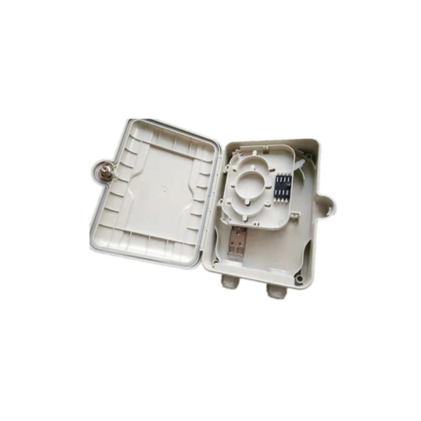
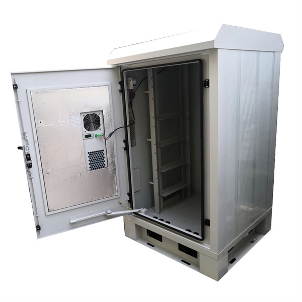
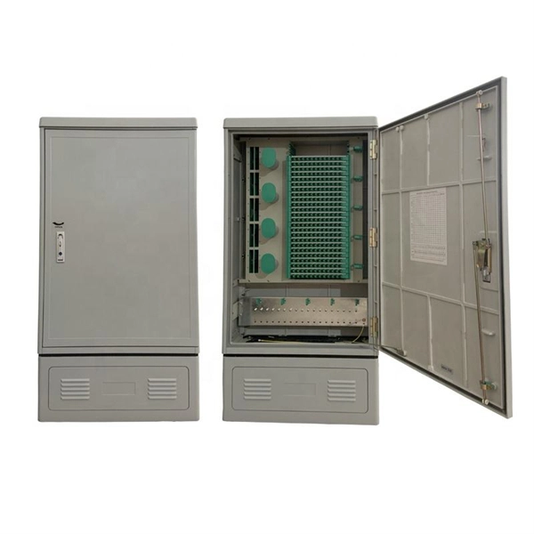
A distribution box serves as a central point for managing and distributing fiber optic cables. This device ensures reliable and efficient connectivity between various network components. Cables with and without connectors can be routed, sealed with IP54 (acc. to 60529) and strain relieved in accordance with EN 62444. It is the central electrical supply system of any. In modern electrical systems, cable distribution boxes (also known as electrical distribution boxes or distribution boxes) play a crucial role as the key hub for managing, distributing, and protecting circuits. Whether it is residential buildings, commercial facilities or industrial sites, the. Electrical systems power our homes, offices, and industrial facilities, but behind every reliable electrical setup lies a crucial component that often goes unnoticed: the distribution box. This essential piece of equipment serves as the nerve center of your electrical system, managing power flow. The box is a closed container made of metal or plastic, which contains various electrical components, such as circuit breakers, contactors, relays, etc. They work together to realize the distribution, control and protection of electrical energy. box are usually installed on the walls of buildings.
[PDF]
This report presents a comprehensive overview of the Belarusian cable trays and ducts market, the effect of recent high-impact world events on it, and a forecast for the market development in the medium term. Jeetmull Jaichandlall (P) Ltd. is one of the trustworthy Cable Tray Manufacturers in Belarus that is here to fulfill all your wire mesh and netting tools needs. We believe in building fruitful business partnerships. Every buyer chooses us first because of our excellent finishing and high-quality. Brilltech Engineers Pvt. These excellent Galvanized Cable Trays that we offer are very popular in the market. Started back in 1983, Cable House is a recognized name engaged in manufacturing and supplying wide range including Hose Clamps, Cable Ties, Crimping Tools, Cable Tray, Industrial Connectors and more, to the national as well as the international market. With our manufacturing expertise, we have even. Keep your cables safe and organized with our high-quality cable trays. Cable Trays are important for ensuring the protection of the wiring system and supporting insulated electric cables used for distribution and communication. Brilltech Engineers Pvt. Ltd is one of the trusted Cable Tray.
[PDF]
Cable laying services install fiber optic cable or copper cable in buildings and office complexes, or over large distances. They are staffed by cable technicians who perform cable preparation, jointing, termination, testing, commissioning, maintenance, and troubleshooting tasks. Installing fiber optic cables underground involves far more than digging trenches and placing cables. It forms a critical backbone for modern communication networks across both urban and rural environments. Project success depends on careful planning, precise installation practices, and proper. Installing underground fiber optic cables is critical to establishing high speed internet infrastructure that delivers reliable connectivity for businesses nationwide. Unlike traditional copper systems, fiber optic cables require specialized handling techniques and precise installation methods to. These skilled professionals ensure that your home or business is equipped with the latest fiber optic technology, providing blazing-fast Internet speeds and robust connections. This guide walks you through the entire process of fiber cable installation, from the initial assessment to the final. This involves burying or installing fiber-optic cables along predetermined routes. During this phase, locators identify existing utilities to prevent damage.
[PDF]

Regularly testing fiber optic cables helps minimize network downtime, lengthens the network's longevity, reduces maintenance requirements, and helps support network reconfiguration and upgrades. Fiber optic testing ensures the performance and reliability of fiber optic networks. Key tests include: Effective fiber testing utilizes advanced tools such as Optical. Fiber optic testing for continuity is crucial in ensuring that light transmits through fiber optic cables without interruptions, safeguarding seamless data transmission. This guide talks about the primary methods and tools for effective continuity testing in fiber optic cable networks. Insertion loss testing confirms whether the cable meets design loss budgets. OTDR testing identifies events along the fiber length, including: OTDR is essential for long-distance FTTH feeder and distribution cables. After the cables are installed and terminated, it's time for testing. For every fiber optic cable plant, you will need to test for continuity, end-to-end loss and then troubleshoot the problems. If it's a long outside plant cable with intermediate splices, you will probably want to verify the. We'll explain why it's vital to test fiber optic cables, the three most popular methods, and when you should use them. Why Testing Fiber Optic Cables Matters? Regular testing of fiber optic cables is not just a preventive measure; it's an.
[PDF]

This standard covers the construction, mechanical, electrical, and optical performance, installation guidelines, acceptance criteria, test requirements, environmental considerations, and accessories for a nonmetallic, all-dielectric self-supporting (ADSS) fiber optic cable. An All-Dielectric Self-Supporting (ADSS) cable operates without metallic messengers, relying entirely on its aramid yarn strength members. For a typical 12-fiber ADSS cable with a 8. AFL-ADSS® (All-Dielectric Self-Supporting) cable is ideal for installation in distribution as well as transmission environments. This guide provides general recommendations for the selection of methods, equipment, and tools for the stringing of ADSS (All Dielectric Self-upporting) fiber optic cables including short and Long Span ADSS cables. The installation methods for ADSS cables are essentially the same as those used for. This Installation Manual is a recommendatory installation document provided by HANGZHOU ZION COMMUNICATION CO. The installation manual is established based on the newest issued international standards such as lEEE Std 1222: 2004, "lEEE standard for all-dielectric. Round aramid reinforced ADSS cable for intermediate and long spans, 4 – 96 fibres. VDE: A- DF 2Y (ZN) 2Y This specification covers a family of optical cables with 4 - 96 fibres for intermediate and long spans.
[PDF]

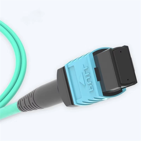
A fiber optic ring network is a physical or logical network topology where devices (usually switches) are connected in a closed-loop using fiber optic cables. Each node is connected to two other nodes, forming a ring-like structure. This design ensures data can travel in both. In this article, we'll explain how to connect multiple Ethernet switches using fiber optic cables and the equipment required for this to work. Network topology refers to the way in which the links and nodes of a network are arranged in relation to each other. If one. Other than entry level network switches, most of today's network switches include one or more GiBC (Gigabit Converter) or SFP (Small Form-factor Pluggable) slots. SFP modules insert into these slots and and require two strands of fiber, typically duplex Using multi mode fiber (for runs under 1000. Fiber optic cabling is increasingly used to connect network switches and other datacom equipment, especially in long-distance and mission-critical applications. Fiber provides: Increased internet signal bandwidth. Most modern fiber-enabled network switches require an SFP transceiver module. Connecting a switch to a fiber optic network involves several steps and requires specific equipment to ensure a successful and efficient connection. Fiber optic technology is widely used in networking due to its high-speed data transmission capabilities and long-distance coverage. This guide will.
[PDF]
Indoor cable (PVC or LSZH jacket) is cheaper but unsuitable for wet or UV-exposed environments. Fiber optic cables are essential components in today's broadband, FTTx, and data center networks. Whether you're planning a national fiber rollout or sourcing cables for enterprise infrastructure, understanding how fiber optic cable pricing works can help you budget more effectively and make better. Buyers typically pay for fiber optic cable by length, fiber type, and installation complexity. Main cost drivers include cable grade (indoor vs outdoor, armoured), distance, and labor for trenching, splicing, and termination. This guide presents ranges in USD and practical price estimates to help. Optic cable price represents a crucial consideration in modern telecommunications infrastructure, reflecting the complex interplay of manufacturing costs, technological advancement, and market demand. These essential components of digital communication networks vary in price based on several key. * Disclaimer: Prices fluctuate based on raw material indices (Glass/Copper/Polymer) and cable core count (e. This feature makes them ideal for high-voltage power lines where both grounding and data transmission are needed. On the other hand, standard fiber optic cables 4 focus solely on data transmission and are.
[PDF]
A grid networks consist of an interconnected grid of circuits, energized from several primary feeders through distribution transformers at multiple locations. Grid networks are typically featured in.
[PDF]
The digital optical audio cable by AmazonBasics is among the best there is in the market. I highly recommend this product to everyone looking for a dependable Toslink cable. You can conveniently connect an.
[PDF]

To use a power meter for fiber optic testing, always clean connectors first with lint-free wipes or click-to-clean tools. Select the correct wavelength and set your reference. You measure optical power in dBm or insertion loss in dB. Consistent procedures ensure accuracy. Verify light travels from. The most basic fiber optic measurement is optical power from the end of a fiber. This measurement is the basis for loss measurements as well as the power from a source or presented at a receiver. Typically both transmitters and receivers have receptacles for fiber optic connectors, so measuring the. An optical power meter measures the strength of light traveling through a fiber optic cable, giving you a reading in dBm (decibels relative to one milliwatt). This article will guide you through the methods, instruments, and key considerations for measuring fiber. Fiber optic cabling is the high-performance core of today's datacom networks. As network speeds and bandwidth demands increase, fiber performance requirements have become more stringent. Fiber testing is more important than ever. An OPM uses a photodiode to generate an electrical current proportional to optical power.
[PDF]

Indoor armored fiber optic cable are the latest networking infrastructure need. The cables provide ultimate mechanical protection, fire protection, and ease of installation, and thus they are suitable for indoor applications such as offices, data centers, and homes as well. These cables are suitable for both indoor and outdoor applications. Other specialized metal designs include square lock armored, spiral. In environments with high crush risk, rodents, or moisture, standard cables are not enough. What is an Armored Fiber Optic Cable? An. Supported applications include gigabit, 10 gigabit, and 40 gigabit Ethernet. Unsure Which Cables Will Suit Your Needs? What speeds and applications will this indoor armored tight-buffered plenum cable support? With bend-insensitive optical fibers (except OM1), this armored fiber optic cable is. These indoor fiber optic cables are used exclusively within buildings and must have a flame-retardant cable jacket to fit this purpose. Flame resistant cable may be deployed in-duct (conduit) or cable tray. Right selection of. Armored fiber cable is a fiber optic cable reinforced with additional protective layers to enhance its durability and resistance to external damage. These cables are designed to endure extreme environmental conditions, physical strain, and potential interference. The armor typically consists of.
[PDF]