KPC operates a ninety-six (96No. ) core Fibre Optic Cable (FOC) that runs along the oil pipeline. KPC was licensed by the Communications Authority of Kenya (CAK) in 2018 to offer FOC services to telecommunications firms in the form of dark fiber leases. The government is set to save Ksh 170 billion through a deal between the Kenya Power Company and the Ministry of ICT, utilizing Kenya Power's transmission lines to roll out 100,000 kilometres of fibre optic cable across the country. The Information Communication and Technology Ministry has revealed that the government is set to save billions by using Kenya Power to create an internet connection. In the new deal which was announced by Energy Minister Davis Chirchir, Kenya Power is set to undertake the connection of fibre optic. KPC operates a ninety-six (96No. By utilizing Kenya Power's transmission lines for the rollout of 100,000 kilometers of fibre. Kenya Pipeline Company (KPC) as part of business diversification and to meet their ever-increasing bandwidth demand for voice, data and video, obtained a Network Facility Provider (NFP) - Tier 2 Network Infrastructure License in 2018 from Communications Authority of Kenya (CA) to lease Fiber Optic.
[PDF]
Broadcast fiber systems utilize fiber-optic technology to transmit video, audio, and data signals over long distances with minimal loss of quality. Unlike traditional copper cables, fiber-optic cables use light to carry information, enabling faster data rates. A submarine communications cable is a cable laid on the seabed between land-based stations to carry telecommunication signals across stretches of ocean and sea. The first submarine communications cables were laid beginning in the 1850s and carried telegraphy traffic, establishing the first instant. Fiber optic technology, with its ability to deliver digital, high-bandwidth, and low signal loss data streams is ideally suited to cope with these needs. To accommodate these growing needs, Fiber Savvy offers a range of fiber optic broadcast products that are specifically designed to withstand the. Fiber optic infrastructures offer the advantage of higher bandwidth, optical signal clarity and more reliable real-time transmissions, enabling providers to service even more applications for emerging technologies such as 4K and 8K ultra high-definition television (UHDTV), Internet-protocol. Explore new highlights of OCC's extensive fiber optic cable, hybrid cable, and connectivity product line—designed specifically for the growing needs and requirements of the broadcast industry. Amphenol Fiber Systems International (AFSI) offers the most complete suite of fiber optic solutions for the broadcast market.
[PDF]

Fiber optic cables offer superior performance compared to copper cables, especially over long distances. They provide higher data transmission rates, larger bandwidths and are immune to electromagnetic interference. Fiber optic cables and copper wires are the two primary types of cables used in networks. Fiber optic cables transmit data using light waves, enabling higher. Fiber optic tends to be the more premium solution, while copper wiring is far more common, but why is that? What are the differences between these two cable types, and why might you want to pick one over the other? Here's everything you need to know about fiber vs. Copper wire is more susceptible to interference and has limited data capacity, making optical fiber the preferred choice for modern high-speed. If you're deciding between copper and fiber optic cables, it's not just a question of cost, it's about purpose, environment, and future readiness. Both have distinct strengths that can serve very different networking needs depending on your setup. Fiber optic cables provide. In today's fast-paced digital world, choosing the right network cable can significantly impact the performance, reliability, and security of your communications infrastructure. Among the most commonly used cables are copper and fiber optic cables, each offering unique advantages depending on the.
[PDF]

Towers are not rooted by only pouring concrete—they require extensive soil analysis, wind loads, types of towers, and seismic activity to determine the necessary foundation for safety and sustainable use. A communication tower foundation design is the structural blueprint that determines the anchor point of the tower on the ground. This article delves into the intricate process of civil construction tailored. Tower owners must comply with a multi-layered regulatory, engineering, and safety framework that governs tower siting, where a cell tower can be built, how it must be designed, and how it operates throughout its lifecycle. These requirements ensure public safety, structural integrity, regulatory. Here are six foundation types for communication towers that work for a wide range of situations and environments. If you're planning a new installation, knowing the basics of these foundations can help you establish a secure and durable tower that will be a community asset for years to come. Telecom (Telecommunications) towers are a generic description of radio masts and towers built primarily to hold telecommunications antennas. As such antennas often have a large area and must be precisely pointed out, such towers have to be designed and built to limit wind induced movement. The Contractor shall employ a quality control program that will ensure that engineering, fabrication.
[PDF]
We calculate cable tray weight using the formula: Volume × Material Density. The calculation accounts for side rails, rungs, and cross-bars. Find the volume of the cable tray: This depends on the dimensions (width, height, thickness) and length of the tray. Multiply the volume by the material density: This gives you the total weight. Now, let's look at the specifics of Cable Tray Weight Calculation for each tray type. 00 for bare tray weight. Used only when cover is selected. Used to estimate joints/couplers. Set to zero if unknown. Typical 200–300 mm spacing. rung bar. The calculation of cable tray weight relies on the following formula: Weight (kg) = Material Density (kg/m³) × Total Volume (m³) To apply this formula, you need: Material type profoundly influences tray weight and suitability. Below is a reference for common materials and their densities, crucial. Height of the Cable Tray You Have: mm Weight Capacity of the Cable Tray You Have: kg/m RESULTS Total dia of all cables: 0. 00kg/m Width of all cables: 0. 00mm YOUR SELECTION ANALYSIS WIDTH CHECK: HEIGHT CHECK: WEIGHT CHECK: REMAINING CABLE. When installing a cable tray, it is vital to make sure that the correct weight capacity of the tray is determined. Calculating the weight of a cable tray is not always.
[PDF]

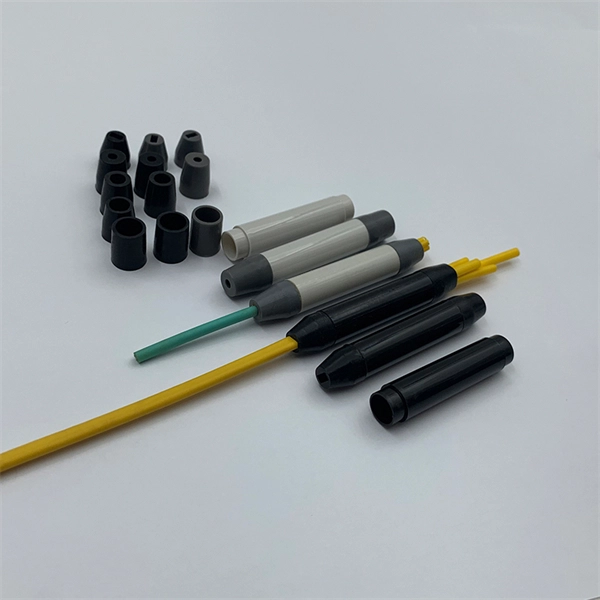
In short length cables a visual fault locator (VFL) can find where the cut is or find the bad connector at patch panels. For longer distance cables, the use of an OTDR is required. Once the fault is located, fusion splicers and splice-on connectors can be used to complete the repair. Fiber optic cables are the backbone of modern networks, delivering fast and reliable data transmission. Accidental cuts, breaks, or other damage can disrupt your network and cause costly downtime. With the right tools and techniques, you can efficiently repair damaged fiber cables and restore. Fiber optics offers advantages like EMI immunity and low attenuation (0. 2 dB/km), but it's fragile—susceptible to breaks, bends, and contamination. Repairs focus on restoring the light path with minimal signal loss (<0. A fusion. Visual inspection and specialized tools like OTDRs, OPMs, and VFLs are essential for identifying and locating physical damage or faults in fiber optic cables. Emergency restoration planning involves implementing backup power solutions, network redundancy planning, and strategies for prompt. Fiber optic cables are critical components of modern communication networks, transmitting vast amounts of data at lightning speeds.
[PDF]
Glass fiber and plastic fiber is fragile. When individual fibers break, light transmission and uniformity are reduced. After the first few fibers break at a stress point, a chain reaction occurs, hastening t.
[PDF]
Optical cable tray is a system designed to protect and route fiber optic patch cords, cable assemblies to and from network cabinets, ODF and other terminal devices. Ducting offers ideal solutions for optical raceway requirements and application with pleasing appearance and easy. Our Fiber Cable Tray System is a comprehensive raceway solution for data center, enterprise, central office, and mobile switching center applications. Designed to route and protect fiber optic and high-performance copper cabling to and from network cabinets, distribution frames, and other terminal. Cable trays are a foundational part of this infrastructure, offering a secure, scalable, and organized method of managing fiber routing across diverse environments.
[PDF]
Click Systems tab Electrical panel Cable Tray. From the Type Selector, select the cable tray type, with or without fittings. On the Options Bar, specify the width, height, offset, or bend radius. more. I am preparing Cable Tray Drawing where i need to provide Cable tray tags on each tray. for that I have Modified default tray Tag family as per my requirement. I use “Comment” Parameter to to tag my cable trays. in my Model there are many Trays and it is very much lengthy and time consuming task. Understand how to model a cable tray using the systems tab in the electrical section for effective coordination, especially in the electrical room. Learn how to set the middle elevation, draw through the room, avoid conflicting elements, and create a detailed and clear visualization of the cable. Sized for the cable fill of the runs it carries. Above lights, below ducts — coordinate with ceiling plenum. Tees, crosses, and reducers handle every direction change. Noble Desktop's Revit MEP Certification Course covers Revit fundamentals — a strong foundation before specializing in mechanical. Join this channel to get access to perks: This lesson walks through how to start a project and properly set up for Electrical Cable Tray design in Revit 2025. It focuses on template selection, component availability, and basic setup steps. Start With the Right Template Opens a new project and.
[PDF]
Schiavetti Tekno, part of Spina Group, is a leading Italian manufacturer of cable trays and accessories for electrical and instrumentation systems. Since 1964, the company has supplied high-quality solutions for industrial cable management in energy, infrastructure, and plant engineering sectors. Recommended maximum length among supports 5,5m. Italy's cable tray manufacturing sector plays a vital role in the nation's infrastructure development. Their expertise ensures reliable cable management systems. Cable tray manufacturers in Italia have established themselves as leaders in cable management solutions, meeting the needs of diverse industries. From energy to construction, these manufacturers deliver high-quality products that ensure efficient and safe electrical wiring management. These products are designed to carry heavier cable loads compared to the. Our cable trays are made of first-class stainless steel (AISI 316 and AISI 304) that prevents corrosion and ensures a good level of resistance. Cable trays from SILTEC are available with a length of 3000 mm. The width varies from 25 mm to 600 mm and the height from 25 mm to 125 mm. Cable trays of a.
[PDF]
Per‑unit estimates often appear as $0. 50 per ft for basic fiber plus additional charges for trenching and install labor. Several drivers shape fiber installation pricing. Homeowners and businesses typically pay for fiber optic cable installation based on distance, conduit needs, and labor. The main cost drivers include material type, run length, trenching or aerial work, and any required permits or inspections. This guide provides clear cost estimates, price ranges. The initial cost of installing fiber optic cables can vary depending on the chosen installation method and specific project requirements. Total Project Costs: For commercial installations, expect costs ranging from $5,000 to $20,000 per mile for underground projects and from $40,000 to $60,000 per. Buyers typically pay for fiber laying by combining material costs, labor time, and permitting plus trenching or aerial support fees. A short residential drop under 1,000 ft may cost $3,000-$8,000, while longer runs to an attached garage or street node can run $8,000-$25,000. The price often reflects project scope, geography, and local regulations, making. Fiber optic cable costs vary widely – from $0. Installation can be more expensive than the cable itself, especially with site challenges.
[PDF]

You can't directly connect a fiber optic cable to your router. You need an intermediary device. The key component is an Optical Network Terminal (ONT) or Optical Network Unit (ONU). Why Use Fiber Optic Internet? Before diving into the setup, let's quickly recap why fiber optics are worth the effort: Lightning-fast speeds (up to 1 Gbps or higher). Low latency for. The process to connect fiber optic cable to router requires careful attention to detail, but I'll walk you through every critical step with the precision and clarity you deserve. This comprehensive guide combines industry standards with field-tested practices to ensure you achieve a rock-solid. The fiber optic cable does not plug directly into a standard home router because the signal type must be translated. Our Experts are helping user's, who are facing issues with their tech gadgets like Router, Modem and extender. Here's a step-by-step guide to help you through it. Understand the Basics Before diving in, familiarize yourself with the components involved:. Connecting a fiber optic cable to a router involves a few key steps and specialized equipment. Check Your Fiber Optic Equipment Before you start, make sure you have the necessary equipment: Fiber Optic Modem (ONT – Optical Network Terminal):.
[PDF]
Fiber optic cables use total internal reflection to keep light signals bouncing within the core, allowing data to travel quickly and with minimal loss. An optical fiber is comprised of a light-carrying core in the center, surrounded by a cladding that acts to traps light in the. Optical fibers are thin glass rods that use the properties of light reflection and refraction to transmit data over long distances. They actively shuttle data encoded in pulsing light across vast distances using only subtle differences in materials. They consist of three elements as shown in Figure 1: a central core, cladding and a protective coating. Optical fibers operate on the principle of total internal reflection, which. Refraction and total internal reflection (TIR) are the two fundamental optical principles that allow light to propagate through optical fibers over long distances with minimal loss. Understanding these mechanisms is essential for designing, installing, and troubleshooting fiber networks in FTTH. Fiber optic cables use a similar concept to guide light. Fiber optic. Describe the workings and uses of fiber optics. Analyze the reason for the sparkle of diamonds. A good-quality mirror may reflect more than 90% of the light that falls on it, absorbing the rest.
[PDF]
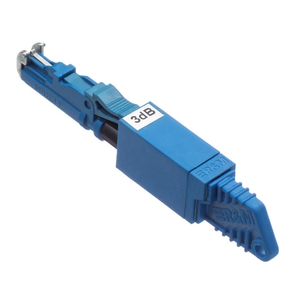
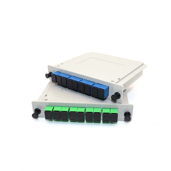
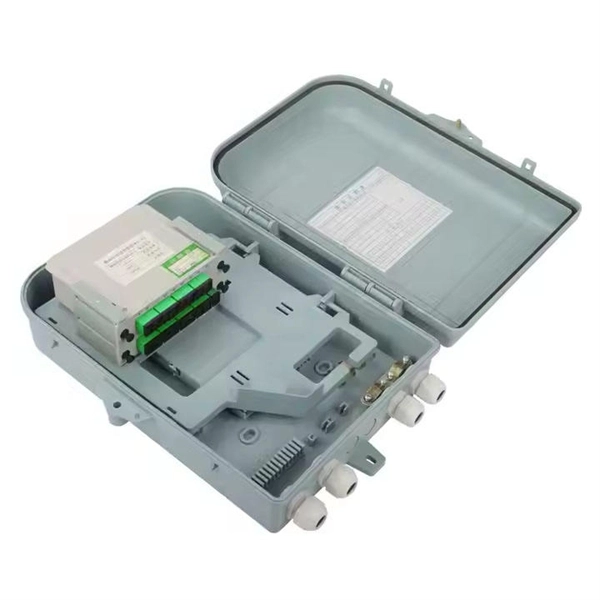
A fiber distribution box (FDB) functions as a central hub in fiber optic networks where the main cable is split into multiple individual fibers for distribution to end users. Fiber Distribution Boxes (FDBs) are critical components in modern telecommunications infrastructure, particularly in fiber optic networks. They function as junction points that manage, protect, terminate, and distribute fiber optic cables, ensuring efficient data transmission between different. According to the definition of YD/T 988-2015, the fiber cabinet is an interface device used to connect the main fiber optic cable and the distribution fiber optic cable outdoors. com/product-category/fiber-optic-cabinet/ the distribution fiber optic cable outdoors. Whether you're a network technician, IT professional, or simply looking to understand fiber optic networks. As a manufacturer of fiber distribution box, Unitekfiber introduce the fiber optic distribution box to you. One side of the optical fiber distribution box is connected to the main optical cable, and the other side is connected to the corresponding fiber optic jumper, which plays the role of fiber. A fiber distribution box operates by converting a distribution cable into individual cables to facilitate the distribution of optical signals to end-users. Here's how it works: Incoming Distribution Cable: The fiber distribution box receives an incoming distribution cable, which typically carries a.
[PDF]
Cable trays can be used in commercial and industrial buildings Firestopped cable tray penetration with teck cables Fire test in Sweden, showing rapid fire spread through burning of cable jackets from one cable tray to another Cable spreading room at Point TupperOverviewIn the of buildings, a cable tray system is used to support insulated used for power distribution, control, and communication. Cable trays are used as an alternative to open wiring or. Several types of tray are used in different applications. A solid-bottom tray provides the maximum protection to cables, but requires cutting the tray or using fittings to enter or exit cables. A deep, solid enclosure for cables i. Common cable trays are made of galvanized,, aluminum, or glass-fiber reinforced plastic. The material for a given application is chosen based on where it will be used. Galvanized tray may b.
[PDF]