
This standard covers the construction, mechanical, electrical, and optical performance, installation guidelines, acceptance criteria, test requirements, environmental considerations, and accessories for a nonmetallic, all-dielectric self-supporting (ADSS) fiber optic cable. An All-Dielectric Self-Supporting (ADSS) cable operates without metallic messengers, relying entirely on its aramid yarn strength members. For a typical 12-fiber ADSS cable with a 8. AFL-ADSS® (All-Dielectric Self-Supporting) cable is ideal for installation in distribution as well as transmission environments. This guide provides general recommendations for the selection of methods, equipment, and tools for the stringing of ADSS (All Dielectric Self-upporting) fiber optic cables including short and Long Span ADSS cables. The installation methods for ADSS cables are essentially the same as those used for. This Installation Manual is a recommendatory installation document provided by HANGZHOU ZION COMMUNICATION CO. The installation manual is established based on the newest issued international standards such as lEEE Std 1222: 2004, "lEEE standard for all-dielectric. Round aramid reinforced ADSS cable for intermediate and long spans, 4 – 96 fibres. VDE: A- DF 2Y (ZN) 2Y This specification covers a family of optical cables with 4 - 96 fibres for intermediate and long spans.
[PDF]

Instead of relying on assumptions, this guide offers a clear-eyed look at how to properly secure your fiber infrastructure, moving beyond the myths to implement practical, layered defenses that provide real-world protection for your organization's most sensitive data. For manufacturers and industry professionals involved in creating, deploying, or maintaining these critical systems, ensuring the robust and reliable securement of fiber optic cables is paramount. “Securing” fiber optic cable goes beyond just preventing it from moving; it encompasses protecting its. Fiber optic cables enable high-speed, long-distance data transfer, forming the backbone of modern communication. Yet, outdoors, they face temperature swings, moisture, UV exposure, rodents, and human interference. Protecting them is essential for long-term reliability. This guide covers how to. Fiber optic and ACSR (Aluminum Conductor Steel Reinforced) cables play a critical role in modern infrastructure, including power transmission and telecommunications. However, these cables face several challenges that can compromise their performance and longevity. If you are an optical engineer or a fiber optic network operator, you need to know how to protect your cables from these threats and ensure. An effective fiber optic network security plan acknowledges these potential weak spots and addresses them head-on. Before beginning any installation, safety.
[PDF]
Corning's ClearCurve bend-improved single-mode fibers provide lower cost, superior installation speed and efficiency, and greater successful installations. 15dB ultra low IL fiber optic cable is less attenuation when bent or twisted compared with traditional bend insensitive fiber cables and this will make the installation and maintenance of the fiber optic cables more efficient. Their market growth is directly tied to the expansion of high-speed internet access and innovative data transmission methods. The global fiber optic cable market is. Gain in-depth insights into Bend Insensitive Fiber Optic Cable Market, projected to surge from $ 1. 5 Bn by 2033, expanding at a CAGR of 7. Explore detailed market trends, growth drivers, and opportunities. 5 USD Million in 2024. The Bend Insensitive Fiber Optic Cable Market CAGR (growth rate) is expected. GL FIBER focuses on optical fiber OEM production services, and is committed to providing customers with brand customization, personalized packaging design, optimal cable structure design, and the best packaging design for international container transportation. GL FIBER® provides the whole series.
[PDF]
adults (49%) say they mostly get news because they happen to come across it, up from 39% in 2019. Over 1,500 new data centers are in development nationwide. Most will be built in rural areas, particularly the South and Midwest, marking a shift from urban. About half of U. Considering how important they are for supporting business operations, ensuring uptime, and enabling scalability, it is a good idea to know what is in a data center, how they work, and. Teens largely turn to TikTok, Instagram and Snapchat for fun and connection. But experiences around messaging, screen time and cyberbullying vary. And what teens say about how these sites impact their mental health. What types of news do Americans seek out or happen to come across? About half of. Data centers are foundational infrastructure for the modern economy. In short, they are the computers we use but don't touch. They power essential services ranging from cloud computing and online commerce to artificial intelligence and secure financial transactions. As the scale and scope of.
[PDF]
This article discusses such episodes, known as data center outages, looks at their causes, and shares best practices for preventing them. Malfunctioning Hardware 3. Environmental and Natural Disasters 6. Software Failure. 2025 revealed how data center outages, from fires and mechanical failures to hyperscale cloud region events, can cascade quickly in an AI-driven world, highlighting the growing importance of physical resilience, control-plane reliability, and clean recovery. Physical infrastructure failures, such. As hyperscale AI campuses expand and real-world attacks strike supporting systems, the gap between how data centers operate and how they're protected is becoming harder to ignore. AWS Outage: What Are the Lessons for Enterprises?. Fault-tolerant systems are systems that are engineered to detect failures, isolate faulty components, and recover quickly without significant impact on operations. This is achieved through a combination of physical, logical, and data redundancy, sophisticated fault detection mechanisms, and. Data center failures can be caused by a variety of factors, some of which are common and impact most people (such as human error), while others are rare. Whether it is rare or not, the impact is usually the same: lost productivity, poor service that affects customers or staff, and costs more. Introduction to Fault Detection through BMS 2. Fault Detection & Diagnostics (FDD): Component Breakdown 5. Predictive &.
[PDF]
In 1880, and his assistant created a very early precursor to fiber-optic communications, the, at Bell's newly established in. Bell considered it his most important invention. The device allowed for the of sound on a beam of light. On June 3, 1880, Bell conducted the world's first wireless transmission between two buildings, some 213 meters apart. Due to its use of an atmospher.
[PDF]
Huawei FusionDC1000C is a prefabricated modular data center solution designed for large public cloud and colocation data centers, optimizing energy use and scalability for enterprise and government applications. In recent years, the rapid progress of AI has prompted various industries to shift focus from digitalization to digital and intelligent transformation. Data centers, as an important carrier of next-generation ICTs like cloud computing, have become the core of modern digital and intelligent. You can deploy your assets in global data centers to rapidly establish IT infrastructure capabilities worldwide. Wide coverage: Data centers are accessible in more than 23 AZs, spanning over 14 countries and regions. You can directly purchase and use the services in these data centers without. To meet these demands, Huawei has launched the Xinghe AI Fabric 2. Built on a three-layer network architecture—AI Brain, AI Connectivity, and AI Network Elements—the solution deeply integrates four core capabilities: Rock-Solid Architecture 2. 0, StarryWing Digital Map 2. 0, Xinghuan AI. Huawei's Smart Data Center Facilities Solution provides a modern foundation for distributed cloud applications. Huawei Cloud provides extremely reliable Tier 3+ equipment rooms and has systematic data center construction specifications. A "One center + Seven layers of defense" security system provides comprehensive and.
[PDF]
Solar energy offers data centers a path to reduce their carbon footprint and operational expenses. Major tech companies like Google and Apple are already leading the way, demonstrating that solar-powered data centers are environmentally responsible and economically viable. Data centers are the backbone of our digital world, powering everything from streaming services and cloud storage to remote work platforms and IoT devices. As our reliance on digital infrastructure grows, so does the energy consumption of these mission-critical facilities. Currently, data centers. Solar offers clean power at predictable costs, can be built fast at many scales, and pairs well with batteries to deliver reliability. In this article, we explain why data centers use so much energy, how solar powers data centers, how batteries and microgrids keep servers online, and why these. 2022 to 35 gigawatts (GW) in 2030. The United States accounts f d tap into suitable energy sources. Renewable energy is the answer, but it must be cost-efective, able to meet enormous demand without inte zed by explosive growth and demand. The emergence of AI, data streaming, cloud computing, and.
[PDF]
Use this distributed feedback lasers buying guide to compare major types, define selection criteria, and find suppliers: Professional purchasing of high-value photonics products is a substantial responsibility, where a structured decision-making process is essential. RP Photonics offers a lot of. Clicking the "Choose Item" drop-down opens a list containing all of the in-stock lasers around the desired center wavelength. LIV and spectral measurements can be downloaded by clicking the red icon corresponding to each serial number. The DFB1550P laser diode is available as a turnkey laser system. DFB or distributed feedback laser diodes are single-frequency laser diodes that usually operate from 783 to 1625 nm (higher wavelength also available). The output wavelength of the DFB laser depends upon the effective refractive index and period of the grating. Covering NIR to LWIR wavelengths (750nm–17µm), these lasers feature integrated DFB gratings and TEC cooling for robust. Distributed Feedback (DFB) and Distributed Bragg Reflector (DBR) laser diodes feature a frequency-selective structure within the laser chip, which restricts the laser emission to a single longitudinal mode. GLSUN designs and manufactures 2. 5Gbps, 10Gbps, and 25Gbps distributed feedback (DFB) laser diode chips for fiber optic transceivers, PON, access, optical Ethernet, SDH, 5G, and data center applications. 5G DFB laser diode chips are available in wavelengths 1270nm, 1310nm 1490nm.
[PDF]
At higher altitudes, factors such as decreased air density, temperature variations, and reduced cooling efficiency can affect the electrical resistance of conductors, leading to potential power losses and reduced system performance. As electrical systems are deployed at various elevations, it becomes essential to understand the potential failures that can occur due to altitude-related factors. In this blog post, we will explore the effects of altitude on electrical equipment based on our experience Photovoltaic Research Base. As power lines are often located at varying elevations, understanding how altitude impacts conductor performance is crucial for optimizing transmission efficiency. Altitude Is A Crucial Factor That Can Significantly Impact The Performance And Reliability Of Electrical Equipment (symbol Image: CLOU) Altitude is a crucial. Heat Dissipation Challenges: Lower air density at altitude significantly reduces the effectiveness of convective cooling. Cables carrying current generate heat (I²R losses). With reduced cooling capability, cables can operate at significantly higher temperatures than at sea level, even for the. Transformers and switchgear get derated at high altitudes, but I have not seen it done for cables.
[PDF]
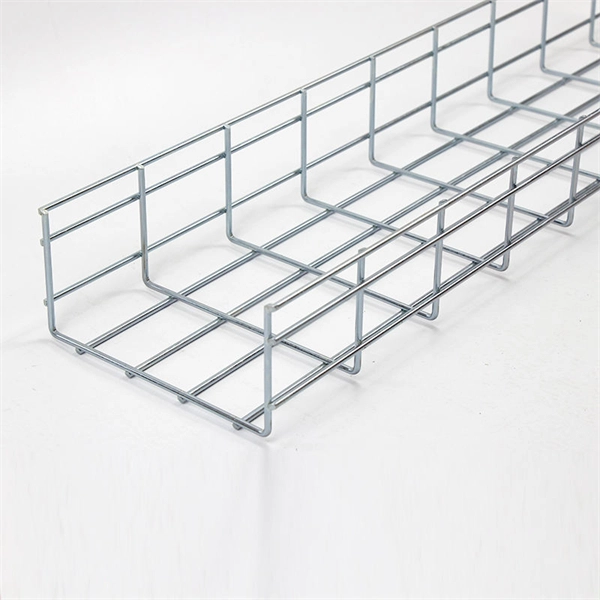
Cable tray is the preferred wiring method for industrial facilities, data centers, and large commercial buildings where routing dozens or hundreds of cables through individual conduits would be impractical and expensive. Question 1: Can mechanical utility piping or tubing containing water or compressed air be installed in cable trays with electrical cables? Answer: No. Cable trays are a support system for electrical cables, power, signal, and communication and optical fiber cables. NEC section 300-8 does not permit. maintain spacing or to keep cables in place when the tray is ect the minimum bend ra-dius for cables as they exit the bottom of the cable tray. The key requirements for cable tray installation include: Incorrect installation can lead to overheating, cable damage, or system failure. This is why proper planning and execution are. Is your cable tray system optimized for safety, dependability, space and cost savings? Cable tray (or cable ladder) systems are a popular alternative to electrical conduit systems, as they have an outstanding record for dependable service, design flexibility and cost savings in commercial and. Article Summary: A compliant cable tray installation requires a thorough understanding of NEC Article 392, proper structural support, and precise installation techniques. This guide covers the critical steps, from selecting the right electrical cable tray and performing accurate cable fill.
[PDF]
Find accurate cable prices in Uganda based on brand, quality, and manufacturer. Compare top suppliers, check MOQs, and get the best deals. Click to explore verified options today!. A 100-meter (328 ft) HDMI fiber optic cable is an active hybrid cable (fiber + copper) designed for. 1M LC_LC DUAL FIBER PATCH CORD: High-performance duplex multimode fiber optic cable with LC. Type: High-speed HDMI 2. Resolution Support: Capable of supporting 4K Ultra HD. Optical Audio Cable, 1. BOX 75720, PLOT NO 6 OPP. VICTORIA UNI (ESSO CORNER), JINJA ROAD, KAMPALA, UGANDA Copyright © Tronic Uganda Limited All Rights Reserved. The Ugandan cable market is rapidly evolving, driven by digitalization and infrastructure development. Prices are tightly linked to brand reputation and manufacturer sourcing, creating distinct tiers. Buyers must navigate between premium international brands, reliable mid-tier options, and. Cable Corporation Ltd was founded in 1968 and is today Uganda's oldest and largest cable and conductor manufacturing company. LV and Domestic Cables, and Transmission Conductors. Cable Corporation Ltd has two divisions. Cable Division and Engineering Division. Entire range of domestic cables – from. Volza's Global Partner Finder scans 3. 5 billion+ shipment records with 20+ precision filters to uncover the most reliable and economical suppliers for you. Volza's data confirms a robust and dependable Optical Fibre Cables supply network.
[PDF]

Find and discover Cable manufacturers and suppliers for all products in Malta, featuring details on their shipment activities, trade volumes, trading partners, and more. View all cable buyers based on products in Malta. Use the full potential of Europe's leading B2B marketplace. Subscribe to global trade data intelligence to discover new business. SM CABLES is a private company duly registered and approved by the local authorities for the Manufacture of Low Voltage Cables and forms part of a group engaged in building construction and electrical trading activities. As a manufacturing base that commenced in 1996, SM CABLES had acquired all the. We supply a range of both indoor and outdoor fibre optic cables that have different construction types, such as tight buffer, loose tube and microcable, to suit different application types be it for direct burial, duct installation, aerial (figure-8 and self-supporting) or blown fibre applications. Network Infrastructure Design, Installations, copper and fibre termination, cable laying, testing and certification. Overhead & Underground Cable Installations and Cable recovery. "At Conversa, our mission is to use our expertise and experience to create an effective and ethical match between the. Who we are, and what we stand for. As a manufacturing base that commenced in 1996, SM (Cables) acquired all the.
[PDF]
If you need fiber cabling installation, termination, splicing, testing, certification, labeling, or repair, you're in the right place. What services do you need? Select all that apply. Your request has been submitted. We'll respond within 24 hours. To gain a competitive edge, your business requires top-of-the-range network cable installation and electric data cabling, and this comes from working with a trusted networking expert such as The Network Installers. We are a local business based in San Jose specializing in communication. We build fiber optic and network cabling infrastructure for businesses across San Jose: structured cabling, low voltage cabling, backbone fiber, MDF/IDF termination, fusion splicing, and OTDR / power meter testing with certification reports. Important: We are not an internet provider. From corporate to residential projects, our certified installers in San Jose, CA ensure a seamless and. San Jose Network Cabling & Wiring is a premier fiber optic cable installer offering a wide range of optical fiber services. Explore our services and discover how we can elevate your network infrastructure today! At San Jose Cabling, we're devoted to delivering outstanding service to each.
[PDF]
Trending price is based on prices over last 90 days. Find many great new & used options and get the best deals for 3M 6366 Hot Melt Fiber Termination Kit 120v Tested at the best online prices at eBay! Free shipping for many products!. Trending price is based on prices over last 90 days. The result is a quick mount. The 8602-S Hot Melt LC is a singlemode. Check each product page for other buying options. Need help?. FS fiber optic pigtails offer a fast way to make fiber optic communication devices in the field by fiber splicing, fully manufactured and tested by industrial standards. 3M Model 6312 Hot Melt Fiber Optic Connector Termination Kit WITH CASE & EXTRAS! item 3 3M Model 6312 Hot Melt Fiber Optic Connector Termination Kit WITH CASE & EXTRAS! Wiha Tools 91872 Master Electrician's Insulated Tool Kit 59 Pc. Find many. TXM's Quick Assembly Hot Melt connectors provide a quick and easy termination of fibers in the field. Our field connectors are universal and applicable for 0. 9mm Tight Buffer Fiber, 2. These field connectors allow the installer to terminate fiber in minutes out in the. Log in or register to view your price, purchase history, and more! The Hot Melt Termination Kit 6366 contains all materials needed to install SC, ST and FC Hot Melt Connectors, both multimode and single-mode. Kit comes with a 120V oven. 3M Hot Melt Termination Kits 6366 (120V oven) and 6362 (230V.
[PDF]
