Receiver sensitivity is the lowest optical power level at which an optical receiver can successfully decode data with acceptable bit error rates (BER). It's a core parameter in optical transceiver specifications, indicating the module's capability to detect weak incoming signals. The standards body governing the application sets this specified BER. For example, SONET specifies that the BER must be 10 -10 or better. What Is BER? The bit error rate (BER) measures the data transmission precision within. Receiver sensitivity stands as a critical parameter impacting an optical transceiver's functionality. It denotes a module's capability to function in challenging environments and aids network operators in determining the system's maximum reach or link margin. Lower receiver. Among a group of optical receivers, a receiver is said to be more sensitive if it achieves the same performance with less optical power incident on it. The performance criterion for digital receivers is governed by the bit-error rate (BER), defined as the probability of incorrect identification of.
[PDF]

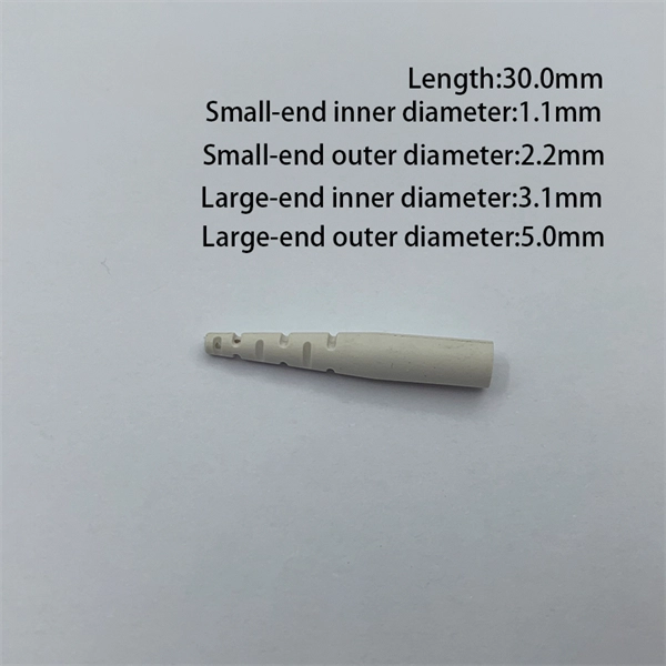
pigtails can be divided into single-mode (colored yellow) and multimode (colored orange) fiber. Multimode pigtails use 62.5/125 micron or 50/125 micron bulk multimode fiber cables and terminated them with multimode fiber optic c. pigtails can be divided into single-mode (colored yellow) and multimode (colored orange) fiber. Multimode pigtails use 62.5/125 micron or 50/125 micron bulk multimode fiber cables and terminated them with multimode fiber optic connectors at one end. 10G multimode fiber cables (OM3 or OM4) are also available in optic pigtails. The jacket color of 10. Fiber Optic Pigtails, In fiber optic cable installation, how cables are attached to the system is vital to the success of network. If done properly, optical signals would pass through the link with low attenuation and little return loss. pigtail offers an optimal way to joint optical fiber, which is used in 99% of single-mode applications. This pos. According to different types of pigtail cable connector terminated at the end, there are LC fiber pigtail, SC pigtail, ST pigtail, FC pigtail, fiber pigtail and so on. With different structures and appearance, each of them has their own advantages in different applications and systems. Let's go through some widely used ones. SC Pigtail: SC pigtail.
[PDF]
ROSA refers to Receiver Optical Sub-Assembly, the primary function of which is to convert the optical signal transmitted from TOSA into electrical signal. ROSA contains a photodiode (PD), optical interface, metal and/or plastic housing, and electrical interface. This article will focus on the internals of the optical transceiver including the TOSA, ROSA and BOSA, and PCBA. Optical modules are devices used to connect network devices, transmit. As a key element in optical communication systems, optical transceivers serve as media between network devices to transmit and receive data. There has been lots of articles and guides on transceiver modules in the perspective of the package type while only a few of them cover the internal elements. Optical transceivers are essential components in modern telecommunications, facilitating data transfer between various network devices by converting electrical signals to optical signals and vice versa. The following section will focus on. An optical receiver is a device that converts light signals traveling through fiber optic cable back into electrical signals that electronic equipment can process.
[PDF]
At the heart of every optical transceiver lie three essential components, often called the “Three Pillars” of optical communication: Laser — generates light. Modulator — encodes data onto the light. Photodiode — decodes light signals back into electrical form. An optical receiver is a device that converts light signals traveling through fiber optic cable back into electrical signals that electronic equipment can process. The core function of the optical receiver relies on a physical phenomenon known as photoelectric conversion. When a modulated light signal. The polarization independent isolator is made of three parts, an input birefringent wedge (with its ordinary polarization direction vertical and its extraordinary polarization direction horizontal), a Faraday rotator, and an output birefringent wedge (with its ordinary polarization direction at. Our optical receivers and detectors make photodetection easy and provide the lowest noise and cleanest response possible. Our broad offering spans wavelength ranges from UV to short-wave IR for free-space and fiber-coupled configurations in many versions: high-speed, general-purpose, balanced. Optical receivers are devices that convert light signals into electrical signals using photodetectors, which come in various types such as photodiodes and avalanche photodiodes. The document covers key concepts such as the operating principles of these detectors, noise types, signal-to-noise ratio.
[PDF]

Our product meets the specification of Cisco® QSFP56-200G-SR4 and we proudly offer a compatibility guarantee and limited lifetime warranty. Carritech Optics delivers high-performance 200G Transceivers designed to provide ultra-fast, scalable, and efficient connectivity for data centres, cloud networks, and telecom operators transitioning to next-generation infrastructures. Unlocking hyperscale and 5G network performance with 200G. QSFP56-200G-SR4 Cisco® Compatible Transceiver QSFP56 200GBase-SR4 (850nm, MMF, 100m, MPO, DOM) ATGBICS Cisco® Compatible QSFP56-200G-SR4 QSFP56 200GBase-SR4 form factor network transceiver supports a distance of up to 100m over multi-mode fibre (MMF) using a wavelength of 850nm via an MPO-12. Worry-Free 30 Day Returns ( Return shipping cost on us) 5-Year warranty (Exchange New) & Lifetime warranty (Repair) Free Trial & Bulk Price Available Late Shipping till 8pm. 5-YEAR WARRANTY Lifetime warranty for repair. 30-Day Money-back Guarantee. Designed in compact form factors such as QSFP56 and QSFP-DD, these transceivers support 200G. Discovery's Coherent Optical Receivers are designed for 100 Gb and upcoming 200 Gb and 400 Gb fiber optic communication systems. Optical Dual Polarization QPSK (DP-QPSK) and 16 QAM modulation formats are detected and converted to electrical signals that can be fed to a digital storage scope, or. Copyright © Chengdu Superxon Communication Technology Co.
[PDF]
In simple terms, Receiver Sensitivity is the minimum received optical power required at the input of a receiver for the system to achieve a specified performance level, typically defined by a maximum Bit Error Rate (BER). Think of it like listening to a distant radio station. The standards body governing the application sets this specified BER. For example, SONET specifies that the BER must be 10 -10 or better. Optical modules form the backbone of modern data center networks, enabling ultra-high-speed data transmission between servers, switches, and storage devices. In optical link design, the receiver performance parameters are like vital signs of the link, directly determining the reliability and. Receiver sensitivity shows the weakest signal your device can find. Good sensitivity gives stronger connections, even with weak signals. Always look at the dBm value in product details. A lower dBm means better receiver sensitivity. This helps you pick the best device. It denotes a module's capability to function in challenging environments and aids network operators in determining the system's maximum reach or link margin.
[PDF]
Our Passive FTTH fiber optic receiver is an essential component for bringing fiber access to households. It is designed for use in FTTH (fiber-to-the-home) networks, enabling analog or digital signal acces.
[PDF]
Xero provides everything you need to succeed, from accounting and invoicing to reporting and payroll Just add prices and quantities, and the template will do the maths for you. For more on how to use this quote template, see our how-to guide (we'll send the link along with the. Here you can get over 10 free quotation templates for New Zealand in PDF, Excel, Word & Google Docs / Sheets formats. All the templates can be downloaded, edited and personalized. What is Quotation Template? Quotation template is a standard layout that contains information in a desirable and. Join World Commerce & Contracting for an engaging and interactive session hosted by Statistics New Zealand, where they will explore what this shift looks like in practice. This session brings together voices from across the commercial lifecycle, featuring perspectives from a graduate, team leader. A Proposal and Quotation document is a formal business document used in New Zealand that combines a detailed. business proposal with specific pricing information. Looking for current tenders, RFQs, RFPs & EOIs? Choose a category and/or enter a keyword and we'll show you the opportunites availabalble. For sole traders and small businesses with up to 2 employees. For established businesses needing to fast track pay runs and inventory. Our AI agents will take care of the.
[PDF]

Source over 605 fiber-optic modules for sale from manufacturers with factory direct prices, high quality & fast shipping. FS provides 1/2/4G transceivers modules in SFP form factor, supporting transmission distances from 100m to 120km over SMF/MMF fiber and enabling low power and cost-effective connectivity solutions. Purchase from nearby warehouses. Trusted by 260K+ Enterprise Users. Fiber optic transceiver modules are fiber cable adaptive housings that contain a light source for transmitting data via fiber optic cable as well as a photodiode for receiving fiber optic data. Mounting options include pluggable CXP, QSFP, SFF, SFP, and XFP, surface or through-hole, CFP, 1x9 SC. This article covers both custom optical elements and custom optical assemblies or systems — beginning with the former. Many optical elements such as lenses, laser mirrors, prisms and diffraction gratings are fabricated as standard parts, i., they are made with the same specifications for many. $ 3,869. 00 Original price was: $3,869. Sale! Sale! Sale! Sale! $ 369. 00 Original price was:. Edmund Optics ® manufactures and supplies customers around the globe with millions of precision optical components and optical assemblies. Our manufacturing capabilities comprise of expertise and resources necessary to manufacture optical products based on your project's specific requirements. Our. TAKFLY COMMUNICATIONS CO. Fiber optical modules Humpal SFP module.
[PDF]

Precast concrete trench systems provide protection and easy access to power, communication, fiber optic, control, and signal wires and cables. Engineered precast trench is used in the power, utility, and transportation industries and can also be used in conjunction with catch basins, inlets, and. Completing Outside Cable Plant Installation. Underground cables are pulled in conduit that is buried underground, usually 1-1. 2 meters (3-4 feet) deep to reduce the likelihood of accidentally being dug up. In extreme cold climates, cables may need to be buried at greater depths where there. THE SOLID APPROACH TO TRENCHING. Made of a unique, patented. Trenwa is the original manufacturer of precast concrete trench and offers the broadest line of proven trench systems. Trusted by Industry Leaders: Trenwa has been a go-to partner for North American infrastructure projects for over for over 60 years. Request a quote today to see how our products can. Waskey's Precast Cable Trench System offers a durable, customizable solution for protecting and organizing critical infrastructure. If you need any help, be sure to reach out. Precast Concrete Trench for underground utility purposes. Primarily used for enclosure of electrical, communication, power cables, and piping.
[PDF]
Connectorized attenuators often have a quite compact housing, essentially looking like a fiber-optic adapter. Some of these devices provide a fixed level of attenuation, quantified as the insertion loss in decibels. An optical attenuator, or fiber optic attenuator, is a device used to reduce the power level of an optical signal, either in free space or in an optical fiber. The basic types of optical attenuators are fixed, step-wise variable, and continuously variable. Optical attenuators are commonly used in. Fiber-optic attenuators are a specific type of optical attenuators which are used in fiber optics, e. for achieving a suitable signal level for a data receiver in a telecom system. It primarily ensures the power or amplitude of a signal is lowered without significantly distorting its waveform. The attenuator circuit will allow a known source of power to be reduced by a predetermined factor, which is usually expressed as decibels.
[PDF]
Convenient Supply Solutions for Oscilloscope Probes Products for resellers and dealers based in Uzbekistan serving Tashkent, Namangan, Samarkand, Andijan, Bukhara, Nukus, Qarshi, Kokand, Chirchiq, Fergana and more. Lenses made from all optical glasses, including Si, CaF2, Ge, ZnSe, ZnS, quartz, and sapphire: Standard lenses in all common designs as well. Optical surface inspection detects minimal defects. This way, you produce your workpieces with consistently high quality. com is a proven supplier of Oscilloscope Probes products dealing major product. According to Volza's Optical,Instrument Import analytics, 698 verified Optical,Instrument buyers in Uzbekistan have imported Shipments from 661 global suppliers. OOO HILBRO accounted for 51% of Uzbekistan's total imports with (1,143 shipments). IP OOO. Compare products based on your own technical specification criteria. How does our search work? With MEET OPTICS search you get direct access to our database of thousands of optical components from providers worldwide. Prices and product specifications directly listed from optical component. Copyright © 2022 GOC-UZ. See our terms of use and privacy policy. Find and discover Optical Equipment buyers & importers for all products in Uzbekistan, featuring details on their shipment activities, trade volumes, trading partners, and more. Subscribe to global trade data intelligence to.
[PDF]

The BA-1 device produces step attenuation of a laser beam to a maximum of about 44 dB . With the preattenuator beam splitter, denoted by SI, this range can be extended as much as another 3 0 dB. The various low level beams generated by BA-1 can be used for detector respon-sivity and. Danielson, B. (1977), Measurement procedures for the optical beam splitter attenuation device BA-1:,, National Institute of Standards and Technology, Gaithersburg, MD, , https://doi. 77-858 (Accessed February 10, 2025) If you have any questions about this publication or. Beam splitters are optical devices that play a crucial role in various scientific and industrial applications. They are used to divide a beam of light into two or more separate beams. NBS interagency report is a publication of the U. The papers are in the public domain and are not subject to copyright in the United States. The BA-1 system is designed for use at. The attenuation ratios of these wavelengths are calculated values. An analysis of the estimated uncertainties is. SPLITTER ATTENUATION DEVICE BA-1 B. Danielson Measurer::ent procedures are described for the step attenuation of laser bearriS up to 44 dB using a specially constructed attenua- tor box (BA-1). a laser beam) into two (or sometimes more) beams, which may or may not have the same optical power (radiant flux).
[PDF]
In 1880, and his assistant created a very early precursor to fiber-optic communications, the, at Bell's newly established in. Bell considered it his most important invention. The device allowed for the of sound on a beam of light. On June 3, 1880, Bell conducted the world's first wireless transmission between two buildings, some 213 meters apart. Due to its use of an atmospher.
[PDF]

To use a power meter for fiber optic testing, always clean connectors first with lint-free wipes or click-to-clean tools. Select the correct wavelength and set your reference. You measure optical power in dBm or insertion loss in dB. Consistent procedures ensure accuracy. Verify light travels from. The most basic fiber optic measurement is optical power from the end of a fiber. This measurement is the basis for loss measurements as well as the power from a source or presented at a receiver. Typically both transmitters and receivers have receptacles for fiber optic connectors, so measuring the. An optical power meter measures the strength of light traveling through a fiber optic cable, giving you a reading in dBm (decibels relative to one milliwatt). This article will guide you through the methods, instruments, and key considerations for measuring fiber. Fiber optic cabling is the high-performance core of today's datacom networks. As network speeds and bandwidth demands increase, fiber performance requirements have become more stringent. Fiber testing is more important than ever. An OPM uses a photodiode to generate an electrical current proportional to optical power.
[PDF]