In this blog, we will explore the step-by-step process of using a beamsplitter cube effectively, along with some common applications that benefit from this powerful optical tool. Step-by-Step Guide on Using a Beamsplitter Cube. 📦 For purchasing, use the RP Photonics Buyer's Guide for beam splitters. It provides an expert-curated supplier directory, buyer-focused technical background information, and structured selection criteria to support professional procurement decisions. What are Beam Splitters? A beam splitter (or. An Optical Beamsplitter is an optic or optical device that is used to split a beam of light in two. Newport offers a wide variety of Beamsplitters in various shapes. It is a crucial part of many optical experimental and measurement systems, such as interferometers, also finding widespread application in fibre optic telecommunications. One beam is typically reflected while the other is transmitted. The ratio of reflected to transmitted light can vary based on the design of the beam splitter. Our plate beamsplitters have a coated front surface that determines the beam splitting ratio while the back surface is wedged and AR coated in order to minimize ghosting and interference effects.
[PDF]
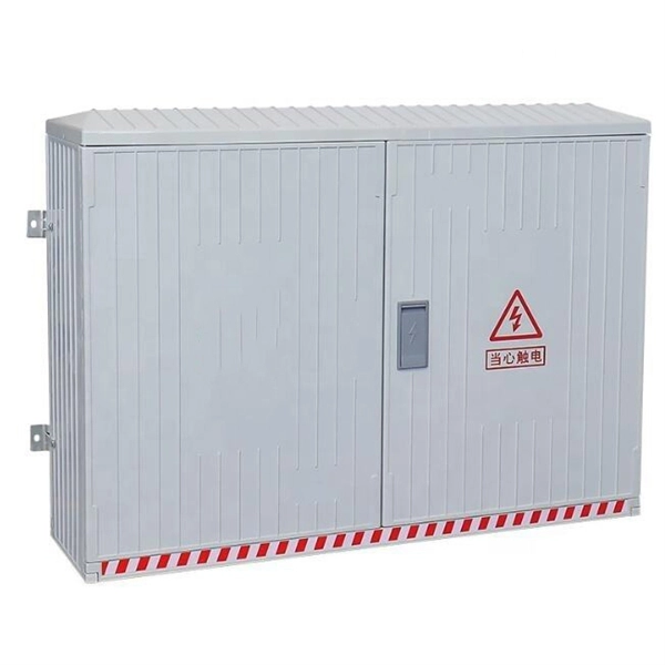
The panel box contains a series of circuit breakers or fuses that control the distribution of electrical energy to individual circuits throughout the building. An electrical panel box, also known as a breaker box or a distribution board, is a crucial component of any electrical system. It serves as a central hub for distributing electricity throughout a building, ensuring that power is delivered safely and efficiently to all the required locations. In this article, we'll explain what a series circuit is, how to draw a series circuit diagram, calculate. A distribution board or distribution box is where the main power supply is distributed to multiple loads. And all the switching and protective devices are installed in the distribution box. Single Phase Distribution Box generally consists of Double Pole MCBs, Single Pole MCBs, and RCCBs. Distribution. STEP 1: The flow of electricity begins at the g nerating station. at S the ation Switchyard. This is done to minimize the losses. STEP3: The ransmission Substation, increases the step-up voltage transformer from 69,000 to 765,000 volts. The distance it will go and the type of facilities distributed.
[PDF]

FRP cable trays offer corrosion immunity, 50% faster installation, and EMI transparency. We cover specifications, standards compliance, and application guidance for engineers. FRP cable tray is a shortened form of fiberglass reinforced plastic cable tray. Cable management infrastructure is a critical but often underspecified element of industrial and commercial electrical. We are a one-stop shop for top-notch Electrical Cable Tray in Senegal. Our cable trays are manufactured from robust materials and rigorously tested to ensure they can withstand even the most demanding environments. We, one of the top Electrical Cable Tray Manufacturers in Senegal, offer a wide. FRP cable tray is the support system for managing cables and protect cables from heating, rains and corrosive elements. They are widely used in chemical plants, building con-structions and residential life by virtue of its. FRP Cable Trays are non-metallic support systems for routing electrical and data cables in industrial and commercial facilities. According to the shape, FRP cable trays can be.
[PDF]

To provide effective and reliable protection to the power system, a protective relay must have the following essential functional characteristics: Selective, Fast, Stable, Reliability, Sensitivity, Simple Construction and Installation Mechanism, and Cost-effective. Characteristics of Protective Relay elements using different operating principles. These principles and design criteria determine how well the basic function is performed and how in practice it deviates from the ideal. These are some essentially. What is a Protective Relay? – Functions, Types & Applications Reliability and safety are paramount in the vast and intricate power systems world. Enter the protective relay, a crucial device designed to detect and respond to abnormal conditions, faults, and disturbances in electrical networks. Types of Protective Relays: Protective relays are categorized by their mechanism (electromagnetic, static, mechanical) and function. A protection relay is a crucial component of electrical systems that safeguard infrastructure, employees, and equipment from electric problems and malfunctions. It functions as a watchdog by constantly surveying multiple system components including voltage, current, frequency, and phase angle. Based on Operating Principle Electromechanical Relays: Work using moving parts and electromagnetic forces (traditional.
[PDF]

Chilean distributors are shifting toward direct partnerships with Chinese manufacturers to gain greater control over pricing, quality, and innovation. By cutting out intermediaries, these distributors ensure a streamlined supply chain that delivers premium Android TV boxes . In the competitive landscape of digital streaming, the role of an Android TV Box Distributor in Chile has evolved far beyond simple importation. Today, distributors are taking a more strategic approach — sourcing Android TV boxes directly from Chinese factories. This decision reflects not only cost. In general, foreign suppliers enter the Chilean market by appointing an agent, distributor, or wholesaler, most of which are small-to-medium size firms. Several large firms handle different product lines and operate as wholesalers. The larger. Market Forecast By Material (Linerboard, Medium), By Printing Ink ( Water-based, UV-curable, Hot melt-based, Solvent-based), By Printing Technology (Digital, Flexography, Lithography) And Competitive Landscape Corrugated boxes are widely used for packaging and transportation of goods across diverse. The rapid growth of smart entertainment has made the role of an Android TV Box Distributor in Chile more significant than ever. As Chilean consumers increasingly turn to digital streaming, local distributors face the challenge of balancing affordability, performance, and availability.
[PDF]