The core measurement procedure follows five steps: Turn on the meter and let it warm up. Most meters need a brief stabilization period before readings are reliable. Check your model's manual, but a minute or two is typical. Set the wavelength to match your light source. Fiber loss is the difference between the power when light is coupled from the transmitting end to the fiber and the power when the light reaches the receiving end. Generally speaking, when measuring the. An optical power meter measures the strength of light traveling through a fiber optic cable, giving you a reading in dBm (decibels relative to one milliwatt). The basic process is straightforward: turn the meter on, set it to the correct wavelength, clean your connectors, plug in, and read the. A power meter and light source are essential test tools that work in tandem to measure fiber optic cable loss and evaluate the quality of optical links. They provide the data necessary to quantify signal loss and pinpoint issues that could impact network performance. Here's how they work: A power. You measure optical power in dBm or insertion loss in dB. Verify light travels from transmitter to receiver. We'll give you the basic information you need and provide some printable references.
[PDF]
Fiber Optic Polarization Extinction Ratio Benchtop Meter for wavelengths from 850 nm to 1650 nm. ER = 30dB for wavelengths from 850 nm to 1290 nm and ER=35dB for wavelengths longer than 1290 nm. Receptacle is not included. Input power is up to 1 mW. Description Handheld Type; 400 to 2400 nm; Extinction Ratio Range 30, 35, 40 dB; Extinction Ratio Accuracy ±1 dB; Angular Accuracy ±0. 5°; Adapter Type FC/PC, ST, E2000. The PEM-400 is an instrument developed for high-volume testing of the polarization extinction ratio (PER) of polarization maintaining (PM) components such as fiber array units (FAU) and external laser small form-factor pluggables (ELSFP). A polarizer is rotated in front of a high-speed power meter. The ERM-202 is a rotating-polarizer polarization extinction ratio meter. It is available in single or dual channel versions. The ERM-202 combines low noise circuitry with a high resolution stepper motor to achieve a PER dynamic range of 50 dB and angle resolution of 0. It is widely used in. It features unmatched low cost, all wavelength options, a large dynamic range, and high resolution. The design adds a rotary polarizer to an optical power meter.
[PDF]
This test station do the auto-testing on 12 core (24 core) for insertion loss and return loss, highly efficient multi-core fiber insertion and return loss measurement and make high precision on the measurement result with OTDR mandrel free technical adopting. (MPO/MTP) mandrel free insertion loss test station is specially design for multi fiber testing. It combines three. •Compact benchtop instrument for all-in-one operation optic components quickly and accurately. The system has a or LED source for multi-mode applications. With a dual two wavelengths in less than 1 second. ILM-100 system comes integration into test systems. the measurement result with OTDR mandrel free technical adopting. Automatically complete the 12-core (24-core) dual-wavelength IL&RL test. The application of OTDR winding-free technology has greatly improved the insertion. You can make an inquiry about this product. Your e-mail will not be leaked.
[PDF]
GELU Systems introduces a new line of intelligent PDUs with switched and metered outlets. Tri-color lighted outlets bring a new level of visual status with 360 degree viewing angle. From basic reliable power distribution to advanced remote monitoring and switching capabilities, find the perfect match for your infrastructure. Network-grade power distribution with individual outlet control, metering, and environmental monitoring. Designed for high-density compute environments. iPDUs serve as a centralized power management solution that enhances the efficiency, reliability, and monitoring capabilities of power. Leaders in rack power distribution units for nearly 40 years, Server Technology PDUs are the choice for Fortune 100 companies to technological startups. Removable display module with front or side mount capability allows easy access to LCD screen and control dial even. PWG2 Intelligent PDU offers advanced power management with real-time monitoring and control. Its features include remote access, customizable alerts, and easy integration, ensuring efficient energy use and reduced operational costs. Ideal for enhancing data center performance and scalability. Powertek is a leading global manufacturer of high-quality, customized rack power distribution units (PDUs), basic and intelligent PDUs, inline meters, automatic transfer switches (ATS), power splitters and environmental sensors for datacenters and IT-professionals. Because power is all we do since.
[PDF]
Thank you very much for purchasing Panasonic products. Read this Instruction Manual carefully and thoroughly for the correct and optimum use of this product. Kindly keep this manual in a convenient place fo.
[PDF]

GOOD WILL INSTRUMENT (SUZHOU) CO. Browse online or download User Manual for Equipment Gw-instek GOS-652G. GW Instek GOS-652G User Manual 50MHz Cursor Readout With Delayed Sweep.. GOS-658G 20MHz Cursor Readout... GOS-652G 35MHz. Caution statements identify conditions or practices that could result in damage to this product or other property. THIS APPLIANCE MUST BE the letter E or by the earth symbol or coloured Green or Green & Yellow. EARTHED The wire which is coloured Blue must be connected to the terminal which is. y have a fraction of the total loss compared to fiber-based equivalents. FBG also provides a latency in the o der of nanoseconds as compared to microseconds in fiber-based solutions. The FBG based DCMs are designed to perfectly mimi the dispersion and dispersion slope characteristic of G. 652 fiber. g sensitivity and low water-peak level. Together they allow unlimited use of the whole telecom wavelength win ow for a great variety of applications.. GOS-653G Basic... GOS-622G. The GOS-653G/652G Series is an example of classic analog oscilloscope design. The GOS-653G /652G cover a broad range of industry applications, such as product design, assembly lines, repair & servicing, and educational purposes for EE laboratories and class experiments. Coupled with various trigger.
[PDF]
We calculate cable tray weight using the formula: Volume × Material Density. The calculation accounts for side rails, rungs, and cross-bars. Find the volume of the cable tray: This depends on the dimensions (width, height, thickness) and length of the tray. Multiply the volume by the material density: This gives you the total weight. Now, let's look at the specifics of Cable Tray Weight Calculation for each tray type. 00 for bare tray weight. Used only when cover is selected. Used to estimate joints/couplers. Set to zero if unknown. Typical 200–300 mm spacing. rung bar. The calculation of cable tray weight relies on the following formula: Weight (kg) = Material Density (kg/m³) × Total Volume (m³) To apply this formula, you need: Material type profoundly influences tray weight and suitability. Below is a reference for common materials and their densities, crucial. Height of the Cable Tray You Have: mm Weight Capacity of the Cable Tray You Have: kg/m RESULTS Total dia of all cables: 0. 00kg/m Width of all cables: 0. 00mm YOUR SELECTION ANALYSIS WIDTH CHECK: HEIGHT CHECK: WEIGHT CHECK: REMAINING CABLE. When installing a cable tray, it is vital to make sure that the correct weight capacity of the tray is determined. Calculating the weight of a cable tray is not always.
[PDF]

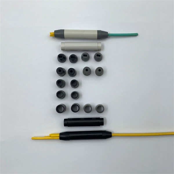
It emits a stable red light driven by a constant current source, which is coupled into the optical fiber through an interface to perform fiber fault detection functions. These include checking fiber connectivity and locating faults such as fiber breaks and bends. The B5 Rechargeable Red Light Pen is a professional 650nm visual fault locator designed for fiber optic network maintenance, installation, and troubleshooting. Its advanced rotary automatic lift laser head ensures smooth operation, while the integrated LED lighting improves visibility in low-light. Luxbond LBTEK Fiber Optic Red Light Pen (also known as a pen-style visual fault locator or fiber optic fault detector) uses a 650 nm semiconductor laser as the light source. Note: Meant for use with polished, terminated fiber cables. Always insert and remove the fiber connector without bending the connector to avoid breaking. The RPEN-210 is a necessity tool that should not be missing from any fiber plant manager or fiber optic installing technician. The Visual Fault Locator (VFL) Pen has a visible red light source centered on 650nm. Tool sends visible light over a fiber strand with a 10mW power, good enough to reach. ● Practical Design: Small size and lightweight, pen-type design with pouch make it portable. Design with a stainless steel head and aluminum body to prevent crash and dust, the case ground design prevents ESD damage efficiently Temp. Only registered users can write questions.
[PDF]

Beamsplitters are capable of dividing the incoming light into several streams. A number of factors impacts this splitting process; for example, the wavelength, intensity, or polarity, or the incoming light; or the construction and settings of the beamsplitter itself. 📦 For purchasing, use the RP Photonics Buyer's Guide for beam splitters. It provides an expert-curated supplier directory, buyer-focused technical background information, and structured selection criteria to support professional procurement decisions. What are Beam Splitters? A beam splitter (or. A beam splitter or beamsplitter is an optical device that splits a beam of light into a transmitted and a reflected beam. It is a crucial part of many optical experimental and measurement systems, such as interferometers, also finding widespread application in fibre optic telecommunications. The first surface is coated with an all-dielectric film having partial reflection properties over either the visible or the near-infrared spectrum. Beamsplitters are often classified according to their construction: cube or plate. Beam splitters are a fundamental element in optical systems. This division allows for the simultaneous analysis or utilization of the light's properties along two separate paths. The device is purely.
[PDF]
Lighting Control System | Smart Lighting Wiring Setup | Full Guide In this video, you will learn how to connect and install a Lighting Control System step-by-step. This guide covers wiring setup, switch modules, dimming control, sensor setup and panel . as a guide for proper and reliable installation. The mounting location should e selected and prepared based on the application. All electrical wiring and mounting hardware (i. ) should be prepared with consideration of the requirements o cuit breaker before. Intelligent Lighting Controls' installation guides provide detailed instructions on how to install all of our solutions. The Lightolier Controls Optio Lighting Control Panels are high-performance, wall mounted lighting control panels which offer a wide range of dimming and relay modules to accommodate any lighting control application.
[PDF]
When encoding diffractive optical elements (DOE) onto a spatial light modulator (SLM), the diffraction efficiency can be reduced because of the pixel nature of the SLM. These effects have been studied previousl.
[PDF]
Solid Green: The ONT is powered on and functioning normally. What to check: Make sure the power cable is securely plugged into both the ONT and a working wall outlet. If you're using a power strip, check that it's turned on. Learn what each light on your fiber equipment means—from power and fiber signal to Ethernet and phone service—and how to quickly troubleshoot issues. This light shows whether your ONT is getting power. No Light: The ONT is not receiving. The Optical Network Terminal (ONT) is a crucial device in modern telecommunications, serving as the interface between your home network and the fiber-optic internet connection provided by your Internet Service Provider (ISP). The ONT has a series of lights that indicate its status and any potential issues. In this article, we will delve into. Power down for 15mins then power back on and wait 3mins for the lights to settle Power connector has come loose. Problem with the plug socket. Optical: This should be a solid green at all times (If the power light is off, this will also. This guide is designed to offer an explanation on how to troubleshoot issues with a CityFibre ONT (Optical Network Terminal). For more help topics, please visit the main Support Page. If you would like details on Freeola Broadband tariffs using the CityFibre Network, please visit our Broadband. You can use the status lights on your optical network terminal (ONT) to help find and fix internet issues. An ONT may also be called a Service box.
[PDF]
Leaders will gather at the World Economic Forum Annual Meeting 2026 to discuss how to protect the environment while also driving economic growth. The next phase of global growth will be shaped by digital intelligence and the energy infrastructure that supports it. The Global Energy Interconnection (GEI) Journal publishes original research on theories and developments as well practical applications on principles of large scale low carbon energy generation, transmission, distribution & storage technologies, global energy interconnection & system developments. The provision of low carbon energy to our society is a key issue at the heart of sustainable development of global energy supply. China's concept of Global Energy Interconnection recognizes the importance of energy inter-connectivity for clean energy transition and repre-sents one of the boldest visions for low-carbon development at the national, regional strial Revolution in the 1870s.
[PDF]
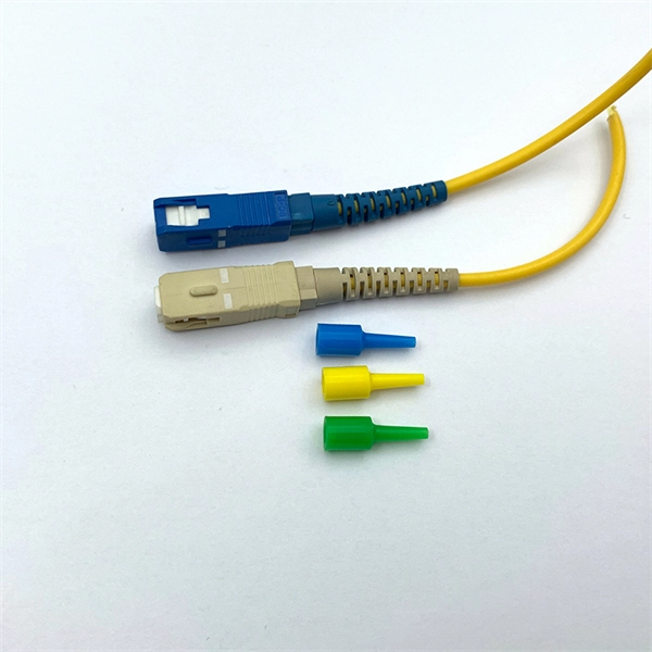
Single-mode optical modules use LD (Laser Diode) or LEDs with a narrow spectral line as the light source. Single - mode optical modules are used for long - distance transmission, generally over 10km, and can reach. Signal Transmission: Single-mode fiber transmits light in a single path. This keeps signal loss and dispersion low for longer distances. Multi-mode fiber disperses light in multiple paths. I've seen people use a single-mode. In fiber-optic communication, a single-mode optical fiber, also known as fundamental- or mono-mode, is an optical fiber designed to carry only a single mode of light - the transverse mode. This article explores what single-mode fibers are, how they are designed, and their applications in various fields. It has a narrow core diameter of 8-10 microns and uses a laser or highly-focused light source to send light signals down the fiber.
[PDF]
If the LOS light on your fiber router or ONT is blinking red, it usually means Loss Of Signal. This guide explains the likely causes, the checks you can do at home, and when the issue needs technician support. The LOS light on your router indicates the status of your internet connection to the Internet Service Provider (ISP). When it's green and steady, everything is fine. However, when it blinks red or stays solid red, it signifies a Loss of Signal, a problem preventing your router from communicating. A red light on your router can be a source of frustration and confusion. Fortunately, diagnosing and resolving these issues doesn't have to be complicated. Before you panic or call tech support, there are several simple fixes you can try at home that often solve this problem in minutes. Here are some steps you can take. You might feel like you're staring into the abyss of digital darkness, wondering what went wrong. But don't despair! This guide will walk you through the most common causes of router.
[PDF]