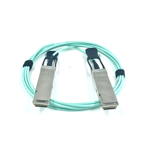
Buy Cisco SFP-10G-SR Gigabit Interface Converter SFP Module online in Nepal at Electronics components store-mystorenepal. com with free home delivery, easy return and cash on delivery. D-TECH Trading is highly recommended for all types of SFP and QSFP modules in the Nepal market. With ready stock, strong technical knowledge, and reliable after-sales support, D-TECH proudly serves major ISPs, Data Centers, Hydropower Projects, and Enterprise Networks across Nepal. 100G QSFP Dual. For bulk orders or B2B inquiries, email us at Click to Email or call us at +977 9849027214. Prices shown are exclusive of VAT and subject to additional VAT. Have a Bulk Order? 【10Gb SFP+ SR】10G SFP+ fiber optical transceiver module, 300m, multi-mode, 850nm, LC, hot plug-and-play slot. 3Gb/s transmission rate, 220m to 120km a variety of transmission distance, the series of optical transceiver use LC optical interface, with low power consumption, small size, high reliability, wide temperature. Discover how QSFPTEK helped PacketStream engineer a reliable 200G DWDM network over 36km using 25G optics, overcoming 100G module scarcity. In this case, QSFPTEK engineers created a 10 Gigabit Ethernet and POP Test Platform Solution by using an OTN managed chassis system. Provide IPRO with a. FS 10GbE SFP+ module solutions provide a wide variety of 10 Gigabit Ethernet connectivity options for data centers, enterprise wiring closets, Internet Service Providers (ISPs) applications. Trusted by 260K+.
[PDF]
HUAWEI WDM replacing the optical module video shows you how to replace an optical module. HUAWEI WDM Documentation:. Single-fiber bidirectional (BIDI) optical modules must be used in pairs. For example, SFP-10G-BXD1 must be used with SFP-10G-BXU1. If the SFP-10G-ER-1310 is connected. SFP Work on Cisco/Huawei/Arista/Juniper/MikroTik/Aruba/H3C/Fontinet/Ruijie etc Check my profile for tips. WhatsApp:86 13528869091 How to disassemble a 10G optical module? How to disassemble a 10G optical module?. Huawei's hn8145x6 idle fish costs more than 400 yuan, which is twice as expensive as the hs8145x6 and k662 previously disassembled. The reason for the price is that 10G Optical fiber module is more expensive, and the CPU is also different. Take down the machine and see what's going on. HUAWEI WDM Documentation:. The SFP (Small Form Factor Pluggable) or SFP+ transceiver is a critical component of fiber optic network cabling. It is used as a hot-swappable I/O device that plugs into a module slot for Gigabit transport. Failure to install an SFP or SFP+ transceiver can cause damage to the transceiver and the. This article will explore best practices for deploying 10G optical modules and offer tips for troubleshooting and maintaining their performance to maximize the longevity and efficiency of your network. Deploying a 10G transceiver requires meticulous planning and adherence to best practices to.
[PDF]

Fiber optic transmission distance varies based on fiber type, environmental conditions, and equipment selection. This guide explores the key factors affecting fiber optic transmission distance and provides practical selection guidelines for a stable and cost-effective network. Receiver Sensitivity Higher receiver sensitivity means that it can detect weaker optical signals. Even if the optical signal power is low, the receiver can still detect and decode the signal correctly, extending the transmission distance of fiber optic communication. Another consideration is that. Fiber optic cable transmission distance is determined by two primary physical factors that affect signal quality as light travels through the fiber medium. For most enterprise or data center applications using multimode fiber, the practical limit sits between 300 m and 550 m. Single-mode. Estimate one-way and round-trip timing for fiber runs, optics, and active hops in home labs and backbone links. Direct point-to-point links with OS2 single-mode 1310 nm typically use 10 km+ of practical reach. Configuration type Fiber profile Route length Measured in feet for imperial mode. Apply a waste factor based on site practice. Click Calculate to see totals and the breakdown. Use the export buttons to share results. For critical links, verify on drawings and allow extra for rework. Fiber length takeoff starts with a measured route. Break the pathway into segments for tray runs.
[PDF]

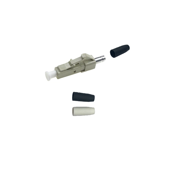
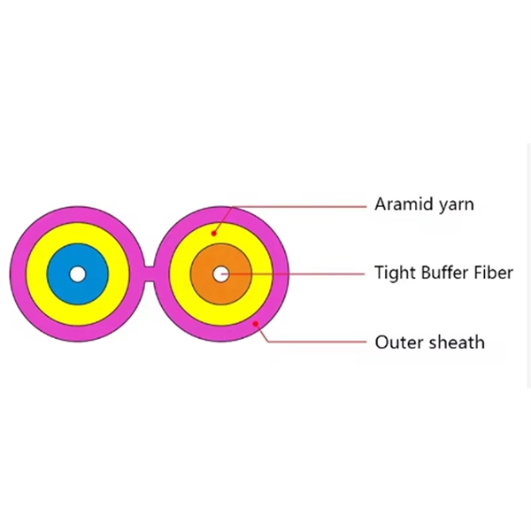
Its typical transmission distance is 20km or 40km. For instance, some ethernet switch manufacturers refer to the 1000BASE-LH SFP as the 1G 1310nm 40km SFP transceiver, which indicates the module's transmission distance and wavelength. The 10G SFP+ dual-fiber optical module is a small pluggable optical transceiver that adopts a dual-fiber bidirectional design. It completes signal transmission (Tx) and reception (Rx) through two independent optical fibers, ensuring the stability and reliability of signal transmission. An SFP (Small Form-factor Pluggable) module transmits data over fiber using specific wavelengths and power levels, which directly influence how far the signal can travel before degradation occurs. This is why two. If the optical module works at a wavelength near 850nm (880nm) or 910nm (940nm), then the module is a multi-mode fiber (MMF) optical transceiver, and if the working wavelength is 1310nm or 1550nm, it is a single-mode fiber (SMF)optical module. Generally, the maximum transmission distance(generally. The transmission distance of optical transceiver modules is divided into short distance, medium distance, and long distance. A 1-core module uses a single fiber core for data transmission, while a 2-core module uses two cores. o Think of a highway. Chromatic dispersion This is a key factor affecting single mode fiber distance.
[PDF]

Fiber optic cable can be run anywhere from 300 meters up to 80 kilometers (roughly 50 miles) depending on the cable type, transceiver used, and network standard. For most enterprise or data center applications using multimode fiber, the practical limit sits between 300 m and 550 m. Fiber optic cable transmission distance is determined by two primary physical factors that affect signal quality as light travels through the fiber medium. The greater the distance, the greater. Many factors decide the fiber cable distance, but the key factors include the below six aspects. Attenuation First is the attenuation of the optical fiber. OM2 extends this to 82 meters. OM1 fiber and OM2 fiber don't support these higher speeds. OM5 fiber matches OM4 at. For instance, without amplifiers, single-mode fiber can reach 50-60 miles and can support data rates of 1 Gbps or 10 Gbps. With amplifiers, such as Erbium-doped fiber amplifiers (EDFAs), the distance can be extended to 600 miles or more, and even further with additional amplifiers for long-haul.
[PDF]
Because of their low cost, low profile, and ability to provide a connection to different types of optical fiber, SFP provides such equipment with enhanced flexibility.OverviewSmall Form-factor Pluggable (SFP) is a compact, network interface module format used for both and applications. An SFP interface on. SFP transceivers are available with a variety of transmitter and receiver specifications, allowing users to select the appropriate transceiver for each link to provide the required optical or electrical reach over. Quad Small Form-factor Pluggable (QSFP) transceivers are available with a variety of transmitter and receiver types, allowing users to select the appropriate transceiver for each link to provide the required optical reach over.
[PDF]

Fusion Splicer Settings – Must-Know for Fiber Technicians! 🔧 At D-TECH TRADING, we're demonstrating the essential Fusion Splicer settings that every fi. more. Auto Mode is the most intuitive and user-friendly splice mode. The fusion splicer automatically detects the fiber type, such as single-mode (SM), multimode (MM), or dispersion-shifted (DS) fibers, and adjusts parameters like arc power and heating time accordingly. Applications: Ideal for beginners. Page 1 Fusion Splicer 19R+/70R+ Quick Reference Guide Splice Operation • When splicing only standard SM fibers (ITU-T G. 652), “SM AUTO” mode is recommended. It also outlines instructions for keypad usage. st Instruction manual Fusion Splicer Please read this instruction manual carefully before operating the equipment. Adhere to all safety instructions and warnings contained in this manual. Keep this manual in a safe place. There is a change without a previous notice. We are not responsible for the. Fusion splicing is the bedrock of high-performance fiber optic networks, enabling seamless signal transmission through permanent, low-loss fiber joins. As a leading provider of fiber optic infrastructure, Weunion leverages cutting-edge tools like the AI9 and AI10 fusion splicers, paired with.
[PDF]
This is where a small but mighty hero comes into play: the Mode Conditioning Patch Cable (MCP). In this guide, we'll demystify what a mode conditioning patch cable is, why it's essential in specific network scenarios, and how it can save you from a world of connectivity headaches. This guide offers the key technical insights you need to select and install the optimal fiber optic cabling solutions for your specific needs. Covers the basics of fiber optic technology, including how light waves transmit data through thin strands of glass or plastic, and why fiber optics surpass. Fiber optic cables use light to transmit data, whereas traditional cables rely on electrical signals, which are more prone to interference and loss over distance. Connector types play a crucial. Fiber optic technology has transformed the way we transmit data, enabling faster, more reliable connections than traditional copper cables. Understanding fiber optic cable types is essential for anyone looking to build or maintain efficient fiber networks. We'll also. This is a plain-English guide for facilities and IT teams who want fiber that performs well, stays organized, and doesn't turn every add/change into a disruption. Start with the link's distance and speed, then pick single-mode (OS) or multimode (OM)—not the other way around.
[PDF]
Talk to our customer service agents today on product availability and get discounted prices from our online SFP Modules store. 1000BASE-T SFP (NEBS 3 ESD). Catalyst 6500 24-port GigE Mod: fabric-enabled (Req. Shopit has the best prices' SFP Modules sale and is a trusted SFP Modules dealer in Rwanda since 2012. We have a track record of giving our customers access to a big variety on the SFP Modules products line, speedy delivery and excellent service. Learn more!. Join An IT Community Designed to Foster Business Growth. Need help? We're happy to answer your questions. Arista 7050X3, 48x25GbE SFP & 12x100GbE QSFP switch, front-to-rear air, 2xAC, 2xC13-C14 cords. 40GBASE-SR4 QSFP Transceiver Module with MPO Connector.
[PDF]
One key aspect of this progression is the advent and evolution of transceivers, specifically SFP, SFP+, SFP28, QSFP+, and QSFP28. Let's delve into each of these technologies to understand their specifications, differences, and applications. A Cisco compatible SFP list 2026 represents a validated inventory of optical transceivers that utilize Multi-Source Agreement (MSA) standards to provide identical functionality to Cisco Original Brand (OB) optics. Deploying these modules allows network architects to reclaim up to 80% of their. —— Explosive Growth of 800G/1. 6T Technologies, Scene-Based Selection + Finisar Original Solutions in One Stop In 2026, driven by AI computing power, optical modules have entered a critical era of rate iteration, technological restructuring, and scenario segmentation. 800G has become the mainstream. Choosing the right Small Form-factor Pluggable (SFP) transceiver is critical for network engineers and procurement specialists aiming to optimize performance, cost, and reliability. This SFP buying guide offers a detailed technical comparison, real-world deployment insights, and practical selection. ity with compelling economics. Our ONE Network platform simplifies management of Cambium Networks' wired and wireless broadband and network edge technologies. Our customers can f iness rather than the network. We mak. SFP+ 10G ZR is designed for stable 80km single-mode transmission where standard 10G optics fail.
[PDF]

When you connect two 1000BASE-T switches with SFP ports to achieve Gigabit Ethernet, there are two methods: through standard Ethernet cable plugged into the built-in Ethernet ports of each switch, or use the SFP ports with a copper SFP module. 🎥 In this video, I show you how to connect two different branded switches using SFP modules and fiber optic cables. Whether you're using Cisco, Planet, TP-Link, D-Link, Ubiquiti, or any other brand — the key is understanding SFP compatibility. Before moving ahead, let us discuss some basics about standard Ethernet cables and 1000BASE-T (IEEE 802. Network topology refers to the way in which the links and nodes of a network are arranged in relation to each other. What Is a 10Gb SFP Module? A 10Gb SFP (Small Form-factor Pluggable) module is a compact, hot-swappable transceiver used to establish high-speed fiber. Did you swap one of the fiber connectors at one of the endpoints? Meaning, take off the housing of the fiber connector, and swap a and b. You'll find SFP / SFP+ specs on the datasheets for the switches. They're free to view and download from Cisco. Cisco also publish a GBIC /. Most modern fiber-enabled network switches require an SFP transceiver module featuring a duplex (two strand) multimode OM3 or duplex single mode OS2 connection with LC connectors. Direct attach cables with pre-terminated SFP connections may also be used. Download the Application PDF SFP transceiver.
[PDF]
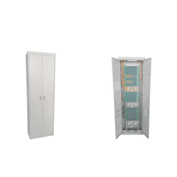
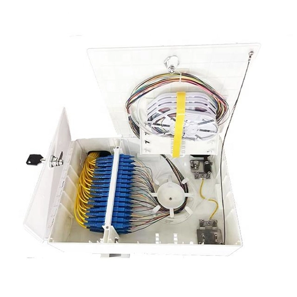
An optical line termination (OLT), also called an optical line terminal, is a device which serves as the service provider endpoint of a. It provides two main functions: 1. to perform conversion between the electrical signals used by the service provider's equipment and the signals used by the passive optical network.
[PDF]
In this part, we explain best practices for import into and exporting out of Cambodia, while highlighting the unique procedures required to ship imported goods through the country on transit clearance.
[PDF]
Understand the core function, compare data rates (1G to 25G), learn critical compatibility rules, and follow our 5-step checklist for selecting the perfect SFP optical module for your network build. SFP (Small Form-factor Pluggable) is a compact, hot-pluggable network interface module used to connect network devices (switches, routers, firewalls) to fiber optic or copper cables. Think of it as the “translator” for your network equipment, converting electrical signals into optical signals. As optical transceiver nerds, we wanted to list some of the most common SFP+ transceiver price lists to help you find the suitable optical transceiver for your needs in the easiest way possible. Optcore is a global supplier of 10G SFP+ transceivers for the ICT industry. Various 10G SFP+ models with. S+31DLC10D is a reliable, industrial-grade 10G SFP+ module designed for long-distance single-mode links up to 10 km. This modular. A practical, engineer-friendly guide to choosing the right transceiver form factor by speed, port density, power, migration plan, and operational risk—built for 25G/100G networks in 2026. 25G SFP28 is the new access/server baseline; deploy it for port density and long-term value. SFP optical modules are the unsung heroes of fiber networking—the essential interface that converts.
[PDF]
The SFP transceiver is not standardized by any official standards body, but rather is specified by a (MSA) among competing manufacturers. The SFP was designed after the interface, and allows greater port density (number of transceivers per given area) than the GBIC, which is why SFP is also known as mini-GBIC. However, as a practical matter, some networking equipment manufacturers engage in pr.
[PDF]