Learn how to monitor SFP optical power on Cisco switches, interpret Tx/Rx levels, and troubleshoot fiber link issues. Step-by-step CLI commands, model-specific guidance, and best practices included. In this article, we will break down the key factors influencing TX/RX power, explain how to calculate the optical power budget, and provide actionable insights for optimizing your network's performance using SFP modules. SFP (Small Form-Factor Pluggable) modules are compact transceivers that allow. SFP (Small Form-factor Pluggable) optical modules are compact, hot-pluggable transceivers that enable network equipment to connect seamlessly to fiber and copper links. Even if an interface appears up, degraded Tx/Rx levels can cause intermittent flapping, packet loss, or err-disabled states. Think of it as the “translator” for your network equipment, converting electrical signals into optical signals. The most two important factors of the SFP transceiver: Output power (TX power) and receiver sensitivity (RX sensitivity). The optical TX power is the signal level leaving from that device, which should be within the transmitter power range. The RX sensitivity is the incoming signal level being. In current network communication, SFP optical modules are an indispensable physical foundation for building network channels. They form high-speed channels for optical signal transmission. Therefore, to ensure their.
[PDF]

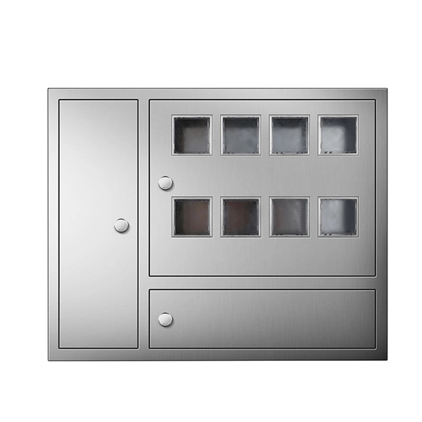
In this video, we'll show you how to connect an energy meter to a distribution board (DB) safely and efficiently. energy meter connection with distribution box How to Connect an Energy Meter to Your Distribution Box Easily Steps to Properly Connect Your Energy Meter to a Distribution Box. It plays a vital role in ensuring the safe and efficient distribution of electricity throughout the premises. What is the wire from the meter to the breaker box? Also. Always begin with disconnecting the main supply before accessing any enclosure containing distribution components. This prevents arc faults and ensures safety when modifying or inspecting current paths. This “meter to panel” wiring establishes the pathway for all incoming electrical power from the grid to the home. Its primary function is to safely and reliably. Distribution Board aslo know as “Panel Board”, “Switch & Fuse Board” or “Consumer Unit” is a box installed in the building containing on protective devices, such as circuit breaker, fuses, isolator, switches, RCDs and MCBs etc. The electric main supply (230V AC & 120V AC in US) is connected through. Changed Texas's reference diagram for the 3 wire network 120/208 Volt single phase self-contained Revised Figures 13, 14, 14b. Limited the meter location from pad mount transformer for PSO. Removed unistrut being listed as an alternative means for mounting the meter box. APCo and TX do not allow.
[PDF]

Select the correct wavelength and set your reference. You measure optical power in dBm or insertion loss in dB. Consistent procedures ensure accuracy. Measure total signal loss from fiber, connectors, or splices. Optical fiber attenuation is the attenuation per unit length of optical fiber, and the unit is dB/km. When connecting two optical fibers, there will be loss inside any connector or joint. Consistent measurement techniques. While optical power meters are the primary power measurement instrument, optical loss test sets (OLTSs) and optical time domain reflectometers (OTDRs) also measure power in testing loss. TIA standard test FOTP-95 covers the measurement of optical power. Optical power is based on the heating power. Light Source: The CMA5 Series Light Sources provide an economical and stable laser source for use in point-to-point attenuation measurement. They feature a rugged design, built to withstand the difficult testing environment of fiber optic cable installation and maintenance. The CMA5 Light Sources. When talking about optical measurements, wavelength basically means how far a wave pattern repeats itself, usually measured in nanometers (nm). Commonly, a power meter on its own is used to measure absolute.
[PDF]

First, inspect the optical module appearance for physical damage, cracks, missing components, poor solder joints, or burn marks. Next, compare voltage, resistance, and waveform parameters between a normal it and the suspected faulty one, both in powered and unpowered states. As core components of optical communication systems, the proper installation and use of optical modules directly impacts network stability. This article systematically identifies common anomalies during optical module installation. However, during installation and daily operation, various issues may arise. The following will introduce the causes of various problems and how to deal with them. Optical module method/step 1. During the test, the value of the module I BiasADC is 0, and the TXLOP-ADC and. These compact devices convert electrical signals to optical signals and vice versa, enabling data transmission over fiber optic cables. While generally reliable, failures do occur, leading to frustrating downtime, performance degradation, and costly troubleshooting. This comprehensive guide details. Have you ever dealt with sudden network drops from faulty optical modules? Issues like this cannot only break communications, but they can really jeopardize business continuity.
[PDF]

A good laser source for a singlemode link will have a power output of ~ +3 to +6 dBm - 2-4mw - coupled into the fiber. Tx power (transmission power) refers to the intensity of the optical signal output by the transmitting end of the optical module. However, in practical use, we adopt the average Tx power. These modules, including SFP, SFP+, and SFP28, are widely used in enterprise networks, data centers, and carrier-grade deployments. Optical loss is measured in “dB” which is a relative measurement, while absolute optical power is measured in “dBm,” which is dB relative to 1mw optical power Loss is a negative number (like –3. 2 dB) while power measurements can be either positive (greater than the reference) or negative (less than. SFP (Small Form-Factor Pluggable) modules are compact transceivers that allow for high-speed communication between network devices. They are essential in applications like telecommunications, data centers, and enterprise networks. Generally, the power levels are specified in terms of transmit (TX) power and. Transmit power is the power at which the transmitter of an optical transceiver module transmits optical signals in dBm. When the signal received is outside of the range, there is a.
[PDF]

The core measurement procedure follows five steps: Turn on the meter and let it warm up. Most meters need a brief stabilization period before readings are reliable. Check your model's manual, but a minute or two is typical. Set the wavelength to match your light source. Fiber loss is the difference between the power when light is coupled from the transmitting end to the fiber and the power when the light reaches the receiving end. Generally speaking, when measuring the. An optical power meter measures the strength of light traveling through a fiber optic cable, giving you a reading in dBm (decibels relative to one milliwatt). The basic process is straightforward: turn the meter on, set it to the correct wavelength, clean your connectors, plug in, and read the. A power meter and light source are essential test tools that work in tandem to measure fiber optic cable loss and evaluate the quality of optical links. They provide the data necessary to quantify signal loss and pinpoint issues that could impact network performance. Here's how they work: A power. You measure optical power in dBm or insertion loss in dB. Verify light travels from transmitter to receiver. We'll give you the basic information you need and provide some printable references.
[PDF]

An optical module's actual transmit power measured by an optical power meter is lower than the nominal transmit power of the power module. The possible causes are: Bores of the optical module are contaminated. Stable optical power is the foundation of every high-capacity optical transport system. Even minor deviations—whether too high, too low, or unstable—can impact signal integrity, trigger service alarms, or interrupt traffic on DWDM, OTN, or long-haul optical line systems. This is the domain of Cell-to-Module (CTM) power loss, a series of. This paper reviews methods for reducing different optical and electrical loss mechanisms in PV modules and for increasing the optical gains in order to achieve higher CTM ratios. Various solutions for optimizing PV modules by means of simulations and experimental prototypes are recommended. Have you ever experienced an unexpected network outage due to the failure of an SFP/SFP+ optical transceiver? Network outages can bring your ability to communicate and work to a halt, and your IT team will likely be frantically looking for a solution. It is important to understand how to. This article provides an in-depth analysis of two key performance indicators of optical modules: transmitter power and receiver sensitivity. Transmitter power characterizes the average optical power output from the laser under rated conditions, while receiver sensitivity indicates the minimum.
[PDF]

The OPM 510 and 520 are available in standard and high-power versions for the Telco and MSO markets. The OPM510 and OPM520 supports wavelengths of 850, 980, 1270 1300, 1310, 1490, 1550, 1577, 1623 and 1650nm. The rugged enclosure provides confidence when testing singlemode and. Count on Tempo Communications Optical Power Meters (OPM510/520) to test and maintain your fiber optic networks. Our optical power meters feature built-in calibration factors. Optical power meters and detectors have been served by Newport for over 30 years. The offering ranges from a low cost, hand-held meter to the most advanced dual channel benchtop power meter available in the market. Our 1936-R/2936-R series boasts state-of-the-art analog boards with a whopping 250. © Copyright© Santec Holdings Corporation. Demo the full range, from multi-use to dedicated PON and FTTH. VIAVI offers fast, cost-effective, and easy-to-use power meters for installation and maintenance of single mode and multimode fiber optic networks and. AFL is a trusted supplier of optical testing equipment with more than 30 years of experience and tens of thousands of units in use in the field. AFL's full range of power meters are used for testing single-mode and/or multimode fiber networks. Power meters with wave ID can detect two or more.
[PDF]

Here's a comprehensive guide to the 15 best optical power meters for fiber techs in 2025, offering expert insights and reviews to help you find the perfect tool for your needs. Also, please take a look at the list of 26 optical power meter manufacturers and their company rankings. Novanta Photonics, 3. What Is an Optical Power Meter? What Is an Optical Power Meter? An optical. | | | | | |. Optical power meters measure the average optical power (energy per unit time) of continuous-wave (CW) or high-repetition-rate pulsed light sources. They are distinct from optical energy meters, which measure the energy of single light pulses, although some consoles support both sensor types. They. Optical power meters and detectors have been served by Newport for over 30 years. The offering ranges from a low cost, hand-held meter to the most advanced dual channel benchtop power meter available in the market. Our 1936-R/2936-R series boasts state-of-the-art analog boards with a whopping 250. HPC-50BVhandheld optical power meter has compactsize and high reliability. It can make accurate measurement on seven operating wavelengths (850/980/1300/1310/1490/1550 /1625nm). ST800K-UC SC/ST/FC Li battery with USB, -70~+10 dbm optical power meter. Optical Power Meters from ADC Corporation are listed on GoPhotonics. Use the filters to.
[PDF]

When you connect two 1000BASE-T switches with SFP ports to achieve Gigabit Ethernet, there are two methods: through standard Ethernet cable plugged into the built-in Ethernet ports of each switch, or use the SFP ports with a copper SFP module. 🎥 In this video, I show you how to connect two different branded switches using SFP modules and fiber optic cables. Whether you're using Cisco, Planet, TP-Link, D-Link, Ubiquiti, or any other brand — the key is understanding SFP compatibility. Before moving ahead, let us discuss some basics about standard Ethernet cables and 1000BASE-T (IEEE 802. Network topology refers to the way in which the links and nodes of a network are arranged in relation to each other. What Is a 10Gb SFP Module? A 10Gb SFP (Small Form-factor Pluggable) module is a compact, hot-swappable transceiver used to establish high-speed fiber. Did you swap one of the fiber connectors at one of the endpoints? Meaning, take off the housing of the fiber connector, and swap a and b. You'll find SFP / SFP+ specs on the datasheets for the switches. They're free to view and download from Cisco. Cisco also publish a GBIC /. Most modern fiber-enabled network switches require an SFP transceiver module featuring a duplex (two strand) multimode OM3 or duplex single mode OS2 connection with LC connectors. Direct attach cables with pre-terminated SFP connections may also be used. Download the Application PDF SFP transceiver.
[PDF]
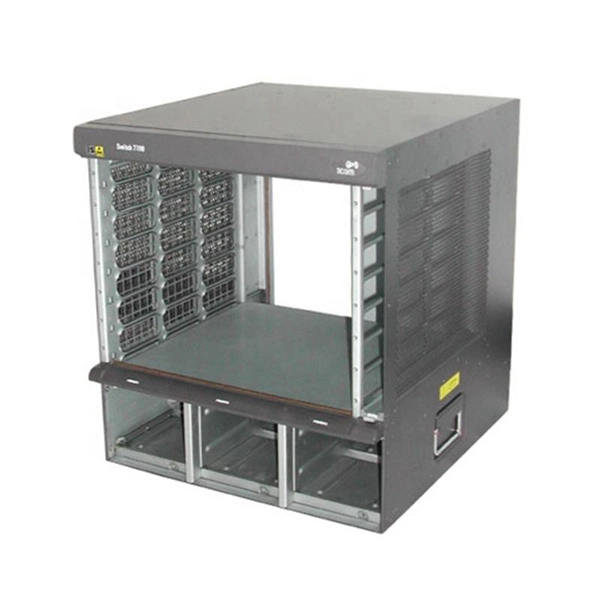
Here you can download the program for the configuration of our electrical cabinets. Written by Schneider Electric's most talented electrical distribution experts, the Electrical Installation Guide is written for professionals who design, install, inspect, and maintain low-voltage electrical installations in compliance with the standards published by the International. Perhaps you need to minimise heat losses to air in a facility without air-conditioning? Many of our most popular DC and AC power systems can be built into IP54 cabinets. An IP54 level of Ingress Protection provides a high level of protection against non-conductive airborne pollutants. Used to house electrical or electronic switchgear, control gear and equipment. The PDU series is designed to meet the needs of power distribution units of telecom access sites. It comes with an integrated controller that enables customer to read tenant-wise energy statistics as well as to extend the remote monitoring access. It is flexible enough to mount in the different. This Electrical Installation Wiki is a collaborative platform, brought to you by Schneider Electric: our experts are continuously improving its content, collaboration is also open to all. DC power is typically used in Data Centres and telecom facilities as it has several benefits. Firstly, DC power can be more efficient than AC power systems as the need for AC to DC conversion is.
[PDF]
will introduce major upgrades to its Multi-Rail technology platform at ECOC 2025, targeting hyperscale optical transport with new efficiency, scale, and performance enhancements. Coherent Corp. SAXONBURG, PA, September 26, 2025 (GLOBE NEWSWIRE) – Coherent Corp. At the heart of the. SAXONBURG, Pa. At the heart of the. Simultaneously, coherent technology has emerged as the prevailing solution for Data Center Interconnection (DCI) applications, covering distances of 80~120km in the field of data communication. These evolving applications introduce new demands for coherent optical transceiver systems, steering the. Coherent optical module refers to a typically hot-pluggable coherent optical transceiver that uses coherent modulation (BPSK / QPSK / QAM) rather than amplitude modulation (RZ/ NRZ / PAM4) and is typically used in high-bandwidth data communications applications. Optical modules typically have an.
[PDF]
Chad Powers is an American television series created by and, starring Powell in the role. Developed from an skit by, the show follows Russ Holliday after he disgraces himself on the field while serving as a star quarterback at a major college program. After ruining his reputation, Holliday undergoes a physical transformation, with the h.
[PDF]

A neat, well-organized subpanel bundles wires to conserve space and improve access. Ideally, wire groups are installed in layers and wires are bent at right angles to buses or breakers. Label short sheathing sections (slugs) to indicate which circuits wires serve. We cover everything from separating color-coded wires and securing them with ties to. Discover 7 DIY tips to organize your electrical panel for improved safety, easier troubleshooting, and efficient maintenance. Prevent hazards while making your home's electrical system more manageable. A disorganized electrical panel isn't just an eyesore—it's a safety hazard and troubleshooting. According to NEC (National Electric Code: Article 1 00-Definitions), a Main Panel (also known as Panelboard, load center, breaker box and distribution board etc. ) is a cabinet or cutout box which contains on controlling and protective devices (such as circuit breakers, fuses, switches etc. ) used to. Welcome to this live training session! ⚡ In today's tutorial, I'll be demonstrating how to arrange cables neatly inside a distribution bo. more See what others said about this video while it was live. If you're struggling with unsightly cords hanging around your cabinets, worry not! In this guide, we'll explore practical strategies to conceal those wires effectively. Before starting the process of.
[PDF]
Discover premium Fiji power adapters with 100% on-time delivery. Shop universal AC DC adapters (5V-24V) for desktop, CCTV, router & more. Durable, multi-plug compatible. [Energy Efficient and Environmentally Friendly]: Not only does the Charger by PowerHOOD deliver impressive performance, but it is also energy efficient. Explore a wide range of our Fujifilm AC Power Adapter selection. Find top brands, exclusive offers, and unbeatable prices on eBay. Shop now for fast shipping and easy returns!. Unleash boundless energy with the BLUETTI AC200P L Portable Power Station, your ultimate power companion for adventures and emergencies alike. 8Wh Capacity with 4,000+ Life Cycles: Perfectly designed for daily power needs or as a reliable backup during outages. Fiji operates on 240V at 50Hz using Type I plugs, the three-pin angled standard found across Australia, New Zealand, and several Pacific nations. US travelers need a plug adapter since American Type A/B plugs won't fit Fiji's outlets. The higher voltage means faster charging for compatible devices. - Rack Height: 4U - Output Connections: (1) Hard wire 4-wire (2P + N + E), (1) Hard wire 3-wire (H N + E) - Nominal Output Voltage: 120V, 200V, 208V, 230V - Nominal Input Voltage: 200V, 208V, 230V, 480V 3PH - Input Connections: Hard wire 3-wire (2P + E), Hard wire 3-wire (H N + E), Hard wire 4-wire.
[PDF]