
While most pigtails are single-fiber, multi-fiber options exist: Single-fiber: The most common (LC, SC, FC). Multi-fiber: 2, 4, 6, 12, 24, 48, or 72 fibers. Multi-fiber pigtails often come in ribbon format for splicing into high-count cables. Traditional Fusion Splice-On Connectors with pigtails provide factory-polished performance with field-termination convenience within harsh environments. Mass fusion splicing can fuse up to all 12 fibers in one ribbon at once. Mass Fusion Pigtails come with all 12 fibers terminated and a ribbonized. By fiber type, there are single-mode fiber optic pigtail and multimode fiber optic pigtail. And by fiber count, 6 fibers, 12 fibers optic pigtails can be found in the market. Fiber pigtails are used in an estimated 99% of single-mode fiber applications worldwide. Despite this ubiquity, they remain a source of confusion for procurement teams and junior installers alike—especially when it comes to connector type selection, polish type, and the tradeoffs between mechanical. Fiber optic pigtails can be divided into single-mode and multimode fibers. Conversely, multimode fiber pigtails, usually orange, use a 62. 5m to 2m—that has a factory-terminated connector on one end and bare fiber on the other end. The connector end is polished and tested under factory conditions, ensuring low insertion loss and high return loss.
[PDF]

A single strand of glass fiber, called single-mode fiber, is used to transmit single-mode or light beams. It can transmit higher bandwidth than multimode fiber but requires a light source with a limited spectral range. There are mainly two types of optical fibers, single-mode optical fiber, and multimode optical fiber, which differ in the way light propagates. The latter is used for short-distance transmission, while the former is typically used for long-distance signal transmission. Please refer to the article. Single fiber modules (BiDi) use one fiber for both transmitting and receiving data. This saves space and money. Dual fiber modules use two fibers. They are easier to set up and give steady communication. Single-mode optical modules are best for long distances and fast speeds. Modes are the possible solutions of the Helmholtz equation for waves, which is obtained by combining. Optical fiber transmission is based on the principle of total internal reflection, where light signals are transmitted through a thin glass or plastic fiber with a core and cladding. The core has a higher refractive index than the cladding, causing the light signal to be reflected back into the. OS1 single mode fiber optic cables are made with a single mode fiber core, which means that they have a very small core diameter of 9 microns. Each type serves distinct applications based on its light transmission characteristics. Very small core (~8–10 µm). Carries one light path (mode).
[PDF]

Not all splitters are created equal. Here are the main types you'll encounter: The "1×N" notation indicates one input fiber and N output fibers. A 1×2 splitter divides the signal into two outputs, while a 1×8 splitter divides it into eight. The more splits, the. By dividing a single optical signal from a central Optical Line Terminal (OLT) into multiple outputs for Optical Network Terminals (ONTs) at users' homes, splitters eliminate the need for dedicated fibers to each residence—slashing infrastructure costs while scaling network reach. This guide. A fiber-optic splitter, also known as a beam splitter, is based on a quartz substrate of an integrated waveguide optical power distribution device, similar to a coaxial cable transmission system. The optical network system uses an optical signal coupled to the branch distribution. The fiber optic. Optical couplers can split or join signals in fibers. You can connect many users to one port with 1:n or 2:n splitters. These devices work both ways, which helps strong network communication. In a Passive Optical Network (PON), a single optical fiber carries massive amounts of data using light. They are named by the number of inputs and outputs, so a splitter with one input and 2 outputs is a 1X2, and a PON splitter with one input and 32 outputs is a 1X32.
[PDF]
Fiber testing is the process of verifying the performance of optical fiber cabling. This process includes a range of tests and measurements such as insertion loss, optical return loss, and fiber length. It encompass.
[PDF]

The main components of a splice box are the splice cassette that picks up the fibers and their reserves, and the front panel which contains different connectors for transmitting signals via copper or fiber optic cables. A splice box (also known as splice distributor) is a housing in which fiber optic cables begin or end. Fiber optics are fanned out in splice boxes that are situated at the end of fiber optic transmission paths. It typically consists of two parts: an outer housing and an internal structure. In this response, we will focus on the. The FSB series of indoor wall mount enclosures are designed for centralized splice-only applications. These boxes are well suited as optical cable splice collection points for DAS (Distributed Antenna Systems), MTU (Multi-Tenant Unit) commercial business applications, and MDU (Multi-Dwelling Unit). Fiber optic splice closures permanently connect two fiber optic cables together and have a splice that protects the components. The optical cable connection part, that is, the optical cable joint, is the part that protects the connection between two or more optical cables by the optical cable. Splicing refers to the permanent connection of two optical fibers to form a continuous optical connection.
[PDF]

Optical connectors are the physical interface that links an optical device to a fiber optic cable. Fiber optics are used in many applications, including medical imaging, automotive, military, industrial, and commercial (e., telecommunications). Each of these. Many people ask the same question: Can you use a fiber optic cable with an RJ45 port? The short answer is no - RJ45 connectors are designed for electrical Ethernet signals, while fiber optics transmit light pulses through glass or plastic. However, modern networks often combine both technologies. An optical fiber connector is a device used to link optical fibers, facilitating the efficient transmission of light signals. An optical fiber connector enables quicker connection and disconnection than splicing. They come in various types like SC, LC, ST, and MTP, each designed for specific. Proper connection of fiber optic cables is essential to harness these benefits fully, as even minor errors can lead to significant performance issues like signal loss. This article will guide you through the necessary tools, materials, and methods on how to connect fiber optic cables effectively. Most SFP fiber optic modules use LC connectors, while SC connectors are mainly found in legacy networks and MPO/MTP connectors are used for high-density cabling rather than directly on standard SFP modules. FC FO LC connectors for fiber optic.
[PDF]
The communication system of fiber optics is well understood by studying the parts and sections of it. The major elements of an optical fiber communication system are shown in the following figure. The ba.
[PDF]

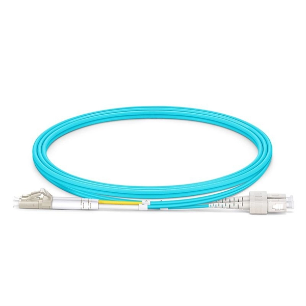
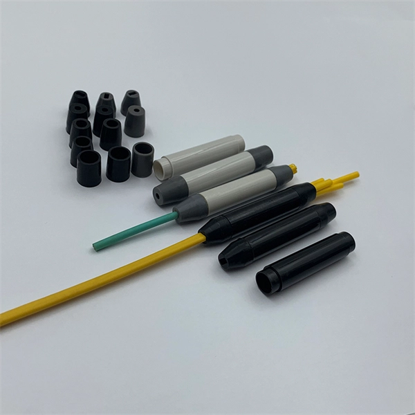
However, essentially, optical fiber patch cords are more like "finished connection lines", while optical fiber pigtails are "semi-finished connectors". The difference in this core positioning determines the vast disparity between them in structure, connection methods. Executive Summary: A fiber optic pigtail is one of the most commonly specified yet least understood components in structured cabling. Get the wrong connector type, the wrong polish, or skip proper fusion splicing technique—and you're looking at elevated signal loss, increased back reflection, and a. When you build or upgrade a fiber network, the same four words pop up everywhere— fiber optic (bare fiber), pigtail, patch cord, optical cable. They're related, but they are not interchangeable. Mixing them up drives costs higher, increases loss, and slows your rollout. The good news? Once you nail. A fiber pigtail is typically a fiber optic cable with one end factory pre-terminated fiber connector and the other exposed fiber. It is usually suitable for field termination using a mechanical or fusion splicer. The connector end plugs into devices like transceivers or patch panels, while the bare end is typically fusion spliced to a fiber optic cable. This setup ensures. As outlined in T13: Fiber Optic Fundamentals, an optical fiber is a coaxial cylindrical dielectric waveguide with a core refractive index exceeding that of its cladding.
[PDF]
Shop cable conduit and interduct for fiber and network cable protection. Ideal for both indoor/outdoor use, this product is easy to install. 1" PVDF Plenum Rated Fiber Innerduct Snap Coupling (for F1-11437 and F1-11437S only). Corrugated, smooth or split wall types. Fiber cable tray/duct is designed to protect and route fiber optic patch cords, multi-fiber cable assemblies, and intrafacility fiber cables (IFC) to and from fiber splice enclosures, fiber distribution frames and fiber optic terminal devices. Our fiber duct/tray is manufacturder with fire. Innerduct is used to protect fiber optic cables as they are routed through buildings or underground. Inner duct product line consists of corrugated HDPE, riser rated PVC and plenum rated PVDF. UL 2024 listed and among the most flexible flame-rated Inner duct products on the market. These ducts are essential for maintaining signal integrity, preventing physical damage, and ensuring long-term reliability in various environments. PVC innerduct conduit is non-metallic, lightweight, corrugated, and flexible to protect and route electrical wire and cables. Note: Product availability. 1-1/4" Diameter, Corrugated HDPE (High Density Polythylene) Innerduct, Orange. Includes: Pull String. No UV Protection, not suitable for outdoor use. Category: Corrugated.
[PDF]

The box is typically composed of several parts, including the enclosure, the splitter module, and the connectors. An optical cable split fiber box is a device used in fiber optic communication networks to split the signal from one input into multiple outputs, allowing multiple devices to be connected to a single fiber optic cable. This provides users with a dependable and high-speed network service and little to no wait times. There is no need for an FDB if there is no. In modern FTTH (Fiber to the Home) and optical communication networks, three types of fiber distribution products are widely used: Splitter Distribution Box, ODF (Optical Distribution Frame), and Fiber Terminal Box. Although they all belong to the optical distribution and management system, their. A fiber optic splitter is a passive optical component that divides a single incoming optical signal into two or more outgoing signals, or combines multiple incoming signals into one. It can divide the input optical signal into multiple output optical signals to meet the fiber optic access needs of multiple terminal devices. This type of device plays an important role in passive. In this kind of fiber cabinet, the backbone fiber optic cable usually does not connect to optical splitters. However, in some metropolitan area, the backbone fiber cable will.
[PDF]
Fiber optic cables use total internal reflection to keep light signals bouncing within the core, allowing data to travel quickly and with minimal loss. An optical fiber is comprised of a light-carrying core in the center, surrounded by a cladding that acts to traps light in the. Optical fibers are thin glass rods that use the properties of light reflection and refraction to transmit data over long distances. They actively shuttle data encoded in pulsing light across vast distances using only subtle differences in materials. They consist of three elements as shown in Figure 1: a central core, cladding and a protective coating. Optical fibers operate on the principle of total internal reflection, which. Refraction and total internal reflection (TIR) are the two fundamental optical principles that allow light to propagate through optical fibers over long distances with minimal loss. Understanding these mechanisms is essential for designing, installing, and troubleshooting fiber networks in FTTH. Fiber optic cables use a similar concept to guide light. Fiber optic. Describe the workings and uses of fiber optics. Analyze the reason for the sparkle of diamonds. A good-quality mirror may reflect more than 90% of the light that falls on it, absorbing the rest.
[PDF]

This helps keep fiber optic cables safe from harm and signal problems when you put them in. Use the right lubricant. Follow the rules for tension and bend radius. Try new methods like air blowing. Use smart. Fiber optic cable is surprisingly strong, durable and pliable; however, several best practices should be followed to ensure a successful cable installation. This article explores recommendations for pulling and installing fiber optic cable. This makes sure the cable pull is smooth and safe. Use smart monitoring devices. The Future Ready Solutions Tools & Test. A duct is available from point A to point B, a pull tape is blown in, a fiber optic cable is attached to it and the cable is pulled through the duct. Sounds simple, doesn't it. Recent observations and conversations with more than a few people in the fiber optic business have indicated. Route plan to ensure the duct run maintains the minimum bend diameter of the cable. For more information and all recommendations for installation, refer to Corning Optical Communications Standard Recommended Procedure SRP 005-011, "Duct Installation of Fiber Optic Cable". more Route plan to ensure.
[PDF]

The basic structure of optical fiber consists of three primary components: the core, the cladding, and the buffer coating. The core is the central part of the optical fiber through which light is transmitted. An optical fiber cable is a complex structure designed to protect fragile glass fibers that transmit digital data using light signals. This advanced cabling solution allows fast, secure data transfer and telecom over long distances. Understanding the components within a fiber optic cable enables. In this blog, we will delve into the fundamental components and structure of optical fiber to gain a better understanding of this revolutionary technology. At its core, optical fiber is a thin, flexible, and transparent fiber made of glass or plastic, which serves as a medium for transmitting light. They consist of three main components and are available in several structures suited to different uses. In this article, discover in detail these components and the various structures of fiber optic cables. The core: made of silica, molten quartz, or plastic, in which optical waves propagate. Dielectric material conducts.
[PDF]

The global fiber optic industry is entering a new pricing cycle. Over the past several months, upstream material costs and supply chain constraints have pushed fiber prices upward, directly impacting cable assemblies, patch cord production, and passive optical components. For distributors, telecom. Since early 2026, the fiber optic cable price has been rising at an extraordinary pace. In some cases, suppliers only guarantee quotations for the same day, and in extreme situations even half-day quotations are appearing in the market. For many professionals who have worked in the optical. See why G. 652D optical fiber prices are rising in 2025–2026, how FTTH cable budgets are affected, and what procurement teams in Europe, Latin America, Africa and the Middle East can do to manage risk. From late 2025 into 2026, global fibre optic prices have increased sharply and across the board — standard single-mode, bend-insensitive grades, and in turn pre-terminated. In 2026, the optical fiber cable industry stands at a pivotal crossroads. After years of market adjustments, ordinary optical fibers are witnessing a 15% price rebound since May 2025, with carrier prices (carrier procurement prices) expected to follow suit. Standard single-mode G. 652D fiber, bend-insensitive G. 657A2 grades have all seen dramatic increases.
[PDF]

Fiber optic network design (896. 83 KB). I'm needing symbols for common fiber optic components, cables, connectors, backbone ports, etc. Can anyone help me out? Some examples of a diagram would also help. 10-27-2018 01:41 AM Do you know if there's some symbol standard fir this kind of schematics? I surely don't know. If you can be helpful. Free CAD and BIM blocks library - content for AutoCAD, AutoCAD LT, Revit, Inventor, Fusion 360 and other 2D and 3D CAD applications by Autodesk. CAD blocks and files can be downloaded in the formats DWG, RFA, IPT, F3D. You can exchange useful blocks and symbols with other CAD and BIM users. See. Search by part number or description such as CAT5, CAT6, OSP, etc. Sort by any of the table headers. Use the drop down menu to filter by product category and type. Sort by any. Welcome to the Corning LANscape® Solutions Product Drawings Resource Center, your complete source for our optical hardware component drawings. The two-dimensional and isometric hardware products drawings are available in PDF (Adobe® Acrobat®), DXF (AutoCAD®), VSS (Visio® Stencil) formats, and. Be among the first to receive important product updates, insights and news. Of all these options, the most favored one is optical cables because they offer uninterrupted swift data transmission.
[PDF]

