
Not all splitters are created equal. Here are the main types you'll encounter: The "1×N" notation indicates one input fiber and N output fibers. A 1×2 splitter divides the signal into two outputs, while a 1×8 splitter divides it into eight. The more splits, the. By dividing a single optical signal from a central Optical Line Terminal (OLT) into multiple outputs for Optical Network Terminals (ONTs) at users' homes, splitters eliminate the need for dedicated fibers to each residence—slashing infrastructure costs while scaling network reach. This guide. A fiber-optic splitter, also known as a beam splitter, is based on a quartz substrate of an integrated waveguide optical power distribution device, similar to a coaxial cable transmission system. The optical network system uses an optical signal coupled to the branch distribution. The fiber optic. Optical couplers can split or join signals in fibers. You can connect many users to one port with 1:n or 2:n splitters. These devices work both ways, which helps strong network communication. In a Passive Optical Network (PON), a single optical fiber carries massive amounts of data using light. They are named by the number of inputs and outputs, so a splitter with one input and 2 outputs is a 1X2, and a PON splitter with one input and 32 outputs is a 1X32.
[PDF]

A single strand of glass fiber, called single-mode fiber, is used to transmit single-mode or light beams. It can transmit higher bandwidth than multimode fiber but requires a light source with a limited spectral range. There are mainly two types of optical fibers, single-mode optical fiber, and multimode optical fiber, which differ in the way light propagates. The latter is used for short-distance transmission, while the former is typically used for long-distance signal transmission. Please refer to the article. Single fiber modules (BiDi) use one fiber for both transmitting and receiving data. This saves space and money. Dual fiber modules use two fibers. They are easier to set up and give steady communication. Single-mode optical modules are best for long distances and fast speeds. Modes are the possible solutions of the Helmholtz equation for waves, which is obtained by combining. Optical fiber transmission is based on the principle of total internal reflection, where light signals are transmitted through a thin glass or plastic fiber with a core and cladding. The core has a higher refractive index than the cladding, causing the light signal to be reflected back into the. OS1 single mode fiber optic cables are made with a single mode fiber core, which means that they have a very small core diameter of 9 microns. Each type serves distinct applications based on its light transmission characteristics. Very small core (~8–10 µm). Carries one light path (mode).
[PDF]

While most pigtails are single-fiber, multi-fiber options exist: Single-fiber: The most common (LC, SC, FC). Multi-fiber: 2, 4, 6, 12, 24, 48, or 72 fibers. Multi-fiber pigtails often come in ribbon format for splicing into high-count cables. Traditional Fusion Splice-On Connectors with pigtails provide factory-polished performance with field-termination convenience within harsh environments. Mass fusion splicing can fuse up to all 12 fibers in one ribbon at once. Mass Fusion Pigtails come with all 12 fibers terminated and a ribbonized. By fiber type, there are single-mode fiber optic pigtail and multimode fiber optic pigtail. And by fiber count, 6 fibers, 12 fibers optic pigtails can be found in the market. Fiber pigtails are used in an estimated 99% of single-mode fiber applications worldwide. Despite this ubiquity, they remain a source of confusion for procurement teams and junior installers alike—especially when it comes to connector type selection, polish type, and the tradeoffs between mechanical. Fiber optic pigtails can be divided into single-mode and multimode fibers. Conversely, multimode fiber pigtails, usually orange, use a 62. 5m to 2m—that has a factory-terminated connector on one end and bare fiber on the other end. The connector end is polished and tested under factory conditions, ensuring low insertion loss and high return loss.
[PDF]

This helps keep fiber optic cables safe from harm and signal problems when you put them in. Use the right lubricant. Follow the rules for tension and bend radius. Try new methods like air blowing. Use smart. Fiber optic cable is surprisingly strong, durable and pliable; however, several best practices should be followed to ensure a successful cable installation. This article explores recommendations for pulling and installing fiber optic cable. This makes sure the cable pull is smooth and safe. Use smart monitoring devices. The Future Ready Solutions Tools & Test. A duct is available from point A to point B, a pull tape is blown in, a fiber optic cable is attached to it and the cable is pulled through the duct. Sounds simple, doesn't it. Recent observations and conversations with more than a few people in the fiber optic business have indicated. Route plan to ensure the duct run maintains the minimum bend diameter of the cable. For more information and all recommendations for installation, refer to Corning Optical Communications Standard Recommended Procedure SRP 005-011, "Duct Installation of Fiber Optic Cable". more Route plan to ensure.
[PDF]

However, essentially, optical fiber patch cords are more like "finished connection lines", while optical fiber pigtails are "semi-finished connectors". The difference in this core positioning determines the vast disparity between them in structure, connection methods. Executive Summary: A fiber optic pigtail is one of the most commonly specified yet least understood components in structured cabling. Get the wrong connector type, the wrong polish, or skip proper fusion splicing technique—and you're looking at elevated signal loss, increased back reflection, and a. When you build or upgrade a fiber network, the same four words pop up everywhere— fiber optic (bare fiber), pigtail, patch cord, optical cable. They're related, but they are not interchangeable. Mixing them up drives costs higher, increases loss, and slows your rollout. The good news? Once you nail. A fiber pigtail is typically a fiber optic cable with one end factory pre-terminated fiber connector and the other exposed fiber. It is usually suitable for field termination using a mechanical or fusion splicer. The connector end plugs into devices like transceivers or patch panels, while the bare end is typically fusion spliced to a fiber optic cable. This setup ensures. As outlined in T13: Fiber Optic Fundamentals, an optical fiber is a coaxial cylindrical dielectric waveguide with a core refractive index exceeding that of its cladding.
[PDF]

If you are ever in need of checking your ONT, this video will show you how to do so and what it is you are looking for. Always remember to securely close the box afterwards to prevent any damage to the facilities inside. more. A fiber termination box is the standard instrument used in fiber optic networks to connect, secure, and protect optical fibers at the terminating point. It functions as a junction between the incoming fiber cable and the outgoing customer-side fiber cable, where one fiber can be spliced, patched. Open the Fiber optic terminal box. Check and prepare installation tools and accessories. Prepare the cable according to the design. An ONT, or Optical Network Terminal, is the box where your fiber internet connection enters your home to power your fiber network. Your ONT is typically located in your garage, basement or outside your home within a few feet of your home's power box. It serves as a termination point for optical fibers, providing a secure and organized space for connecting and managing fiber optic cables. A fiber pigtail is a specific hardware connection used for cable termination. Proper installation and maintenance of FTBs are essential to ensure the reliability and performance of the network infrastructure.
[PDF]

Typical rates range from $0. 00 per ft depending on terrain, access, and required precision for termination. Basic — 1,000 ft single-mode run indoors with minimal termination: Cable $0. 00/ft, Permits $150, Accessories $100. Total ≈ $2,650–$3,100. Fiber-optic cable materials typically cost $1 to $6 per linear foot, depending on fiber count and cable type. Commercial building installations with 100-200 network drops generally range from $15,000 to $30,000. Single-mode fiber costs less per foot than multimode fiber, but it requires more. Buyers typically pay for fiber optic cable by length, fiber type, and installation complexity. Main cost drivers include cable grade (indoor vs outdoor, armoured), distance, and labor for trenching, splicing, and termination. This guide presents ranges in USD and practical price estimates to help. The cost per foot of fiber optic cable is now the lowest it's been since 2021. Labor dominates the installed price. Here is the 2026 benchmark for cost of laying fiber optic cable per foot by method: Open trench (lawn/field): $0. 80 per ft – fastest, lowest cost. Directional boring (road. Single-mode fiber (OS2): This is the industry workhorse. In 2025, the base glass price has stabilized. You are looking at $0. The price swing usually depends on the fiber count (e., 12-core vs 96-core) and brand. This article breaks down the price landscape and provides.
[PDF]
6Wresearch actively monitors the Palau Fiber Optics Cable Market and publishes its comprehensive annual report, highlighting emerging trends, growth drivers, revenue analysis, and forecast outlook. Our insights help. Est. Freight Cost? date (-30 days from arrival). Click here to find out more. Buyers typically pay for fiber optic cable by length, fiber type, and installation complexity. Main cost drivers include cable grade (indoor vs outdoor, armoured), distance, and labor for trenching, splicing, and termination. This guide presents ranges in USD and practical price estimates to help. CRU provides comprehensive, accurate and up-to-date price assessments and research reports for bare optical fibre across various key regional markets, combined with insights into the factors and events affecting markets. How does 6W market outlook report help businesses in making decisions? 6W monitors the market across 60+ countries Globally, publishing an annual market outlook report that analyses trends, key drivers, Size, Volume, Revenue, opportunities, and market segments.
[PDF]

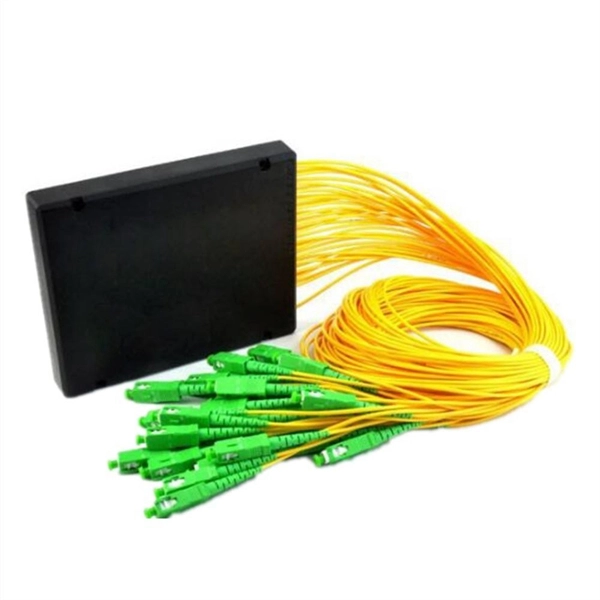
The box is typically composed of several parts, including the enclosure, the splitter module, and the connectors. An optical cable split fiber box is a device used in fiber optic communication networks to split the signal from one input into multiple outputs, allowing multiple devices to be connected to a single fiber optic cable. This provides users with a dependable and high-speed network service and little to no wait times. There is no need for an FDB if there is no. In modern FTTH (Fiber to the Home) and optical communication networks, three types of fiber distribution products are widely used: Splitter Distribution Box, ODF (Optical Distribution Frame), and Fiber Terminal Box. Although they all belong to the optical distribution and management system, their. A fiber optic splitter is a passive optical component that divides a single incoming optical signal into two or more outgoing signals, or combines multiple incoming signals into one. It can divide the input optical signal into multiple output optical signals to meet the fiber optic access needs of multiple terminal devices. This type of device plays an important role in passive. In this kind of fiber cabinet, the backbone fiber optic cable usually does not connect to optical splitters. However, in some metropolitan area, the backbone fiber cable will.
[PDF]

Since the earliest days of fiber optics, multimode cables have typically been color‑coded orange, black, or gray, while single‑mode cables are marked in yellow. For example, cable jacket color typically defines the fiber type, and can differ based on mode and performance level. These colors are typically chosen by industry standards bodies. However, there are some non-standardized colors and inconsistencies that you should be aware of. However, with the introduction of metallic connectors like FC and ST—whose bodies are difficult to color‑code—colored strain relief boots. Multimode fiber (MMF) is a kind of optical fiber mostly used in communication over short distances, for example, inside a building or for the campus. Multimode fiber optic cable has a larger core, typically 50 or 62. 5 microns that enables multiple light modes to be propagated. Because of this, more. Originally developed by the Electronic Industries Alliance (EIA) and the Telecommunications Industry Association (TIA), the TIA-598-D standard (formerly EIA/TIA-598) remains the most recognized color-coding system for optical fibers worldwide. On the right, the yellow patchcord indicates singlemode fiber and the blue connector means it is a regular PC polished connector, If it were an APC connector, it would be green. Perhaps nothing is.
[PDF]

This unit is a nine output Composite Splitter with built in distribution amplifier. It is used to distribute composite video signals to multiple destinations with compatible outputs. Composite Splitter provides multiple outputs that are identical to the Video input signal. Check each product page for other buying options. Shop products from small business brands sold in Amazon's store. Learn more Need help? Discover optical fiber splitters designed for home. Optical splitters and couplers split or combine light—distributing signals injected into a single fiber strand to multiple fibers, enabling point to multi-point communication in Fiber To The Home (FTTH) networks based on ITU. T PON standards such as GPON, XGS-PON and new 25 and 50G standards. Cables Plus USA can supply custom fiber optic splitters to meet your specific requirements. Available in PLC splitters, also called Planar Lightwave Circuit. As well as FBT splitters Fused Biconical Taper splitters, which are two or. Only 1 left! Get the best deals on Corning Cable Splitters and Adapters and find everything you'll need to improve your home office setup at eBay. Fast & Free shipping on many items!. FS PLC Fiber Optic Splitters, Bare/Blockless/ABS/LGX Splitter/Rack Mount Types, support 1xN light distribution, with low IL and PDL for high-reliability transmission. Deploying compact FS PLC Splitters to simplify your networks, perfectly fits your PON, EPON, FTTX, etc. ZIP code to view pricing.
[PDF]
Glass fiber and plastic fiber is fragile. When individual fibers break, light transmission and uniformity are reduced. After the first few fibers break at a stress point, a chain reaction occurs, hastening t.
[PDF]

Mouser offers inventory, pricing, & datasheets for 8 Fiber Fiber Optic Cable Assemblies. Understanding the 8 core fiber optical cable price list is essential for businesses looking to invest in future-ready technology, as prices can vary significantly based on quality, application, and manufacturer. Whether you are a large corporation or a small enterprise, this guide will help you. Pricing (USD) Filter the results in the table by unit price based on your quantity. A tariff of 10% may be applied if shipping to the United States. A. Discover the perfect Optical Fiber addition with our 8 Core Optical Fiber Cable. Choosing OEM custom optical fiber manufacturing lets you specify details and order in bulk, which can drive cheap optical fiber cable pricing. This guide highlights cost-saving order strategies and reliable distributor. There are three primary types of 8-core fiber optic cables, each designed for specific performance needs, distance requirements, and application environments. The key differences between these types include core diameter, light source, transmission distance, bandwidth capacity, and typical use. An 8-core fibre optic cable is a high-density MPO (Multi-fibre Push-On) cable that integrates eight individual optical fibres within a single jacket. Featuring eight individual optical fibers protected by a durable metallic or non-metallic armor layer, these cables.
[PDF]

Fiber optic cables offer superior performance compared to copper cables, especially over long distances. They provide higher data transmission rates, larger bandwidths and are immune to electromagnetic interference. Fiber optic cables and copper wires are the two primary types of cables used in networks. Fiber optic cables transmit data using light waves, enabling higher. Fiber optic tends to be the more premium solution, while copper wiring is far more common, but why is that? What are the differences between these two cable types, and why might you want to pick one over the other? Here's everything you need to know about fiber vs. Copper wire is more susceptible to interference and has limited data capacity, making optical fiber the preferred choice for modern high-speed. If you're deciding between copper and fiber optic cables, it's not just a question of cost, it's about purpose, environment, and future readiness. Both have distinct strengths that can serve very different networking needs depending on your setup. Fiber optic cables provide. In today's fast-paced digital world, choosing the right network cable can significantly impact the performance, reliability, and security of your communications infrastructure. Among the most commonly used cables are copper and fiber optic cables, each offering unique advantages depending on the.
[PDF]

This article provides a detailed technical comparison between fiber optic and copper cables, offering a clear perspective for engineers, network architects, and procurement managers. The core distinction between the two technologies lies in the physics of data. There are significant differences in performance between ADSS cables (all-dielectric self-supporting optical cables) and traditional optical cables, which are mainly reflected in the following aspects: 1. This type of fiber optic cable is designed to support its own weight without the need for additional support structures like messenger wires. The ADSS. There are several factors to assess when deciding which cable type is right for your application, including speed of connection for new customers, ease of changes and repairs, installer certification requirements, and the ability to expand the network over time. ADSS Fiber Optic Cables are a type of optical fiber cable designed specifically for. All-dielectric self-supporting (ADSS) cable is a type of optical fiber cable that is strong enough to support itself between structures without using conductive metal elements. It is used by electrical utility companies as a communications medium, installed along existing overhead transmission.
[PDF]
