A fiber-optic splitter, also known as a, is based on a of an integrated waveguide power distribution device, similar to a The system uses an optical signal coupled to the branch distribution. The splitter is one of the most important in the link. It is an optical fiber tandem device with many input and output terminals, especially applicable to a passive optical network (,,,.
[PDF]

A fiber-optic splitter, also known as a beam splitter, is based on a quartz substrate of an integrated waveguide optical power distribution device, similar to a coaxial cable transmission system. The optical network system uses an optical signal coupled to the. In modern FTTH (Fiber to the Home) and optical communication networks, three types of fiber distribution products are widely used: Splitter Distribution Box, ODF (Optical Distribution Frame), and Fiber Terminal Box. Although they all belong to the optical distribution and management system, their. These include the Optical Line Terminal (OLT), pivotal in initiating the fiber optic signal; the Optical Distribution Frame (ODF), which organizes and manages connections; and the Passive Optical Splitter (POS), responsible for dividing the optical signal to serve multiple premises. Additionally. Fiber splitters and fiber distribution terminals (FDTs) are integral parts of these networks, each serving distinct functions. While both facilitate signal distribution, they possess unique features and applications. Delving into the main differences between fiber splitters and fiber distribution. In the backbone of modern Fiber-to-the-Home (FTTH) networks, optical splitters serve as the unsung heroes that enable cost-efficient connectivity for millions of subscribers. By dividing a single optical signal from a central Optical Line Terminal (OLT) into multiple outputs for Optical Network.
[PDF]
A fiber-optic splitter, also known as a beam splitter, is based on a quartz substrate of an integrated waveguide optical power distribution device, similar to a coaxial cable transmission system. The optical network system uses an optical signal coupled to the branch distribution. The fiber optic. These unassuming devices enable a single optical signal to be divided into multiple paths, making them indispensable for sharing network resources efficiently—from residential FTTH (Fiber-to-the-Home) connections to large-scale telecom backbones. Optical splitter. Fiber optic splitter is a passive optical device used to distribute optical signals, which can divide input optical signals into multiple outputs to meet the fiber optic access needs of multiple terminal devices. Optical splitters are a very important component in fiber optic links, widely used in. They are devices that split an incident light beam into several light beams at certain splitting ratios. The role of these splitters in optical networks is crucial as they allow a single optical signal to be shared among many users, thereby enhancing the efficiency and capacity of the network. Each type serves specific applications, enabling efficient use of optical infrastructure.
[PDF]
Cube beamsplitters eliminate beam displacement without being fragile. They are easy to mount and mechanically durable, but the presence of an interface can limit power handling if epoxy is used for bonding. I am looking for a beam splitter with the following properties: Polarising, so that one path is for p polarised light, and the other path for s polarised. Similar performance across a range of angle of incidence. I have been looking and either I can't find what I am looking for, or I just get. Many people don't know what a beam splitter is and wonder if they need it or not to use a smartphone adaptor on the microscope or slit-lamp. The beam splitter is found on most trinocular microscopes and some slit lamps. The beam splitter splits the light that travels up to the camera in two. A beam splitter (or beamsplitter, power splitter) is an optical device which can split an incident light beam (e. a laser beam) into two (or sometimes more) beams, which may or may not have the same optical power (radiant flux). This division allows for the simultaneous analysis or utilization of the light's properties along two separate paths. One beam is typically reflected while the other is transmitted. The ratio of reflected to transmitted light can vary based on the design of the beam splitter. It is a crucial part of many optical experimental and measurement systems, such as interferometers, also finding widespread application in fibre optic telecommunications.
[PDF]

A beamsplitter is an optic that splits light into 2 directions. The split ratio of light transmittance and reflectance is 1:1 and is called a half mirror. The 2 forms of beamsplitters are cube and plate type. It is a crucial part of many optical experimental and measurement systems, such as interferometers, also finding widespread application in fibre optic telecommunications. In its. The square in the middle is a cube beam splitter in the same orientation for both cases. So, now changing only the beam direction in case. Beamsplitters are fundamental components in optical engineering, serving to precisely divide a single input beam of light into two distinct output beams. This division allows for the simultaneous analysis or utilization of the light's properties along two separate paths. One portion passes through the device while the other reflects off it, and the ratio between the two can be controlled by design. It can be used to direct light in specific directions, or to combine multiple beams of light into one.
[PDF]
Part two of this series provides details on how to build the beam splitter. It is made from regular float glass without any coating. Watch part 1 if you want. This article explains how to create a beam splitter cube in Sequential Mode. One of the biggest challenges for modeling such a system is that multiple ray paths cannot be simultaneously traced in Sequential Mode. Thus, multiple configurations are needed to trace rays along both the transmitted and. Beamsplitters are optical components used to split incident light at a designated ratio into two separate beams. Additionally, beamsplitters can be used in reverse to combine two different beams into a single one. Method A: Diffraction Grating surface and multi-configuration 2. Development steps Inserting general parameters for simulation (wavelength, aperture,. It is a crucial part of many optical experimental and measurement systems, such as interferometers, also finding widespread application in fibre optic telecommunications. In its. T E3 + RE4, where T; R are the transmission and re ection coe cients for the beam splitter. Note that jT j2 is the transmitted intensity. Similarly, E2 ! RE3 + T E4. The transformation matrix is then given by The elements of the beam splitter transformation matrix B are determined using the.
[PDF]

In this case use an optical power meter (OPM) and test the input port of the splitter for the optical power level (dBm) from the OLT at 1490 nm. If there is no or reduced power then the patchcord or OLT is the culprit. If the power level is reduced it could be as simple as a. So for this simple 1X2 splitter, how do we test it? Simply follow the same directions for a double-ended loss test. Attach a launch reference cable to the test source of the proper wavelength (some splitters are wavelength dependent), calibrate the output of the launch cable with the meter to set. Optical splitters in the outside plant (OSP) are used mostly in passive optical networks (PONs) for fiber-to-the-user (FTTx) networks, and are often overlooked as failure points. In this article I focus on a few basics of optical splitters, their applications, typical causes of failures, and how to. Now, we test the simplest 1x2 optical splitter as the picture shown below. 001 dB), OTDR (for reflection event detection). Cleaning tools. The CertiFiber® Pro Optical Loss Test Set (OLTS) can be used to check that the loss of a PON Splitter (often referred to in various standards as a non-wavelength-selective or wavelength-selective branching device) to check that it is within the allowed defined limits. The CertiFiber® Pro has an.
[PDF]
The NanoSpeed™ Series 1×4 solid-state fiber-optic splitter splits the optical power among four outputs with any power splitting ratio. The input is polarization-maintaining (PM) fiber and the outputs are four single mode or PM fibers. Thorlabs offers a wide range of optical beamsplitters. Our plate beamsplitters have a coated front surface that determines the beam splitting ratio while the back surface is wedged and AR coated in order to minimize ghosting and interference effects. Pellicle beamsplitters provide excellent. Beamsplitters are optical components used to split input light into two separate parts. Beamsplitters are also ideal for fluorescence applications, optical interferometry, or life science or semiconductor instrumentation. Light. PLC (Planar Lightwave Circuit) Splitters are designed for single-mode applications and offer an even split ratio from one input fiber to multiple output fibers. Circular beamsplitters, plate beamsplitters and cube beamsplitters can be purchased for polarizing or non polarizing beamsplitting. OZ Optics Online. This is achieved using patent pending non-mechanical.
[PDF]

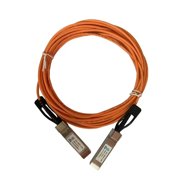
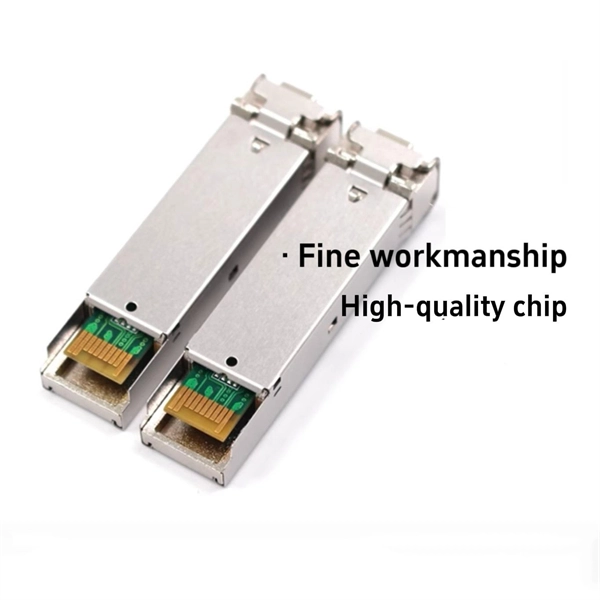
FiberMall MPO16 APC Y Splitter Cables 10m are designed for 800G QSFP-DD/OSFP DR8/OSFP XDR8 optics direct connection and support 800G transmission for Hyperscale Data Centers. Multimode PLC Splitter is a passive optical device used to split incoming signals into two or more output signals. They're capable of operating over a broad wavelength range from 650 nm to 1350 nm (Typ. 650nm, 850nm and 1300/1310nm). 5/125 (OM1, OM2, OM3 and. High-Quality Construction: This Fiber Optic PLC Splitter is manufactured by UT-KING, a reputable brand known for its reliable products, ensuring a durable and long-lasting performance. Optimized for FTTH Solutions: Designed for use in Fiber-to-the-Home (FTTH) applications, this 1x2 OM3 PLC Splitter. Optical coupler is an optical device that combines or splits power from optical fibers. Note: All insertion loss and insertion loss referenced without connectors. Takfly, established in 2000, has been manufacturing. Optional split ration 1:99, 2:98, 5:95, 10:90, 20:80. USource OM3 Fiber Coupler is a 1x2 or 1x3 passvie optical multimode splitter based on FBT (Fused Biconic Taper) technology, packaged in mini ABS box module or steel tube, split into different rations 1:99, 2:98, 50:50, 10:90, 20:80.
[PDF]
A beam splitter or beamsplitter is an optical device that splits a beam of light into a transmitted and a reflected beam. It is a crucial part of many optical experimental and measurement systems, such as interferometers, also finding widespread application in fibre optic telecommunications. DesignsIn its most common form, a cube, a beam splitter is made from two triangular glass which are glued together at their base using polyester,, or urethane-based adhesives. (Before these synthetic,. Beam splitters are sometimes used to recombine beams of light, as in a. In this case there are two incoming beams, and potentially two outgoing beams. But the amplitudes. For beam splitters with two incoming beams, using a classical, lossless beam splitter with Ea and Eb each incident at one of the inputs, the two output fields Ec and Ed are linearly related to the inputs thro.
[PDF]
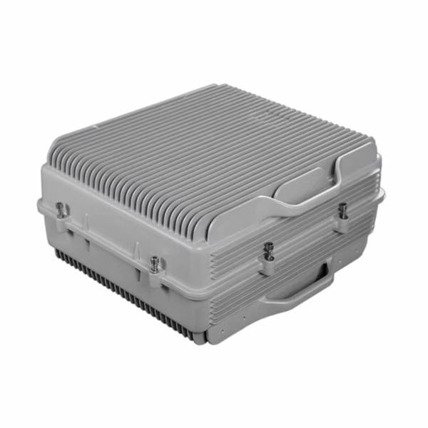
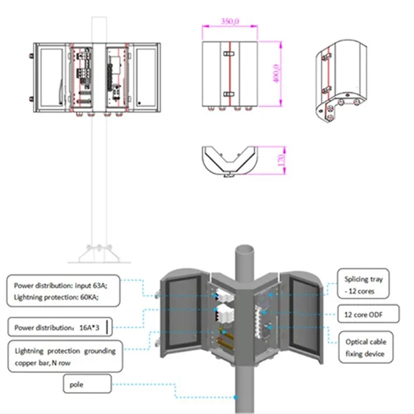
A splitter terminal box serves as a specialized enclosure that manages, splices, and distributes fiber optic cables within modern networks. In modern FTTH (Fiber to the Home) and optical communication networks, three types of fiber distribution products are widely used: Splitter Distribution Box, ODF (Optical Distribution Frame), and Fiber Terminal Box. Although they all belong to the optical distribution and management system, their. A fiber optic splitter is a passive optical component that divides a single incoming optical signal into two or more outgoing signals, or combines multiple incoming signals into one. It is. many aspects of a Fiber to the X (FTTx) network. Splitter architectures can impact fiber counts, splicing needed, numbers of fiber needed, and the customer on-boarding process. conversations and confusion in the industry. of splitting architectures. A “splitter” is a power splitter. A splitter is. This guide will demystify this pivotal passive device, exploring its types, working principles, and how it seamlessly integrates with optical transceivers to bring high-speed internet to your doorstep. 📄 What is an Optical Splitter? An Optical Splitter, also known as a beam splitter, is a passive.
[PDF]
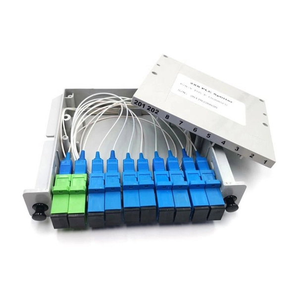
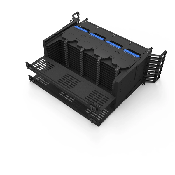
PLC Splitters are based on planar waveguide circuit technology. Inside the splitter, a silica glass substrate routes the incoming optical signal through a waveguide and evenly splits the light into the desired number of outputs. Planar Lightwave Circuit (PLC) Splitter is a type of passive optical component using silica optical waveguide technology to distribute optical signals from the Central Office (CO) to multiple premise locations, allowing for efficient communication. FS Bare Fiber Splitters are engineered for. It is widely used in passive optical networks to realize optical signal power splitting with 1xN or 2xN splitting ratio. Gigalight provides a series of customized PLC splitters to meet different Length, Output Fiber Type, Output Fiber Length, Input connector, and Output Connector etc. All. PLC optical splitters (planar waveguide optical splitter) is a key component in optical fiber communication networks and is widely used in optical fiber distribution systems such as FTTH (fiber to the home) and PON (passive optical network). They are fabricated with silica optical waveguide technology; maintain superior channel-to-channel uniformity and stability through a wide ange of environmental and mechanical conditions. All optical fibers used in Wirewerks PLC splitters are bend.
[PDF]

5 dB depending on splitter type. Common planning value: 0. Optional: patch panels, attenuators, or extra components. Helps cover dirt, aging, and measurement tolerances. Adds Rx power and margin calculation. Calculate insertion loss for passive optical splitters in PON and distribution networks. Power is divided equally among output ports. Excess loss accounts for manufacturing imperfections, typically 0. DISCLAIMER: These calculators are provided for. Optical splitters, encompassing FBT (Fused Biconical Taper) couplers and PLC (Planar Lightwave Circuit) splitters, are prevalent passive optical devices designed to divide fiber optic light into multiple segments based on a specified ratio. Fiber optic splitters are vital components within. In fiber optic networks, particularly in FTTx (Fiber to the x) and PON (Passive Optical Networks) deployments, splitters play a central role in distributing the optical signal from a single source to multiple destinations. Optional: patch. Understanding optical splitter loss isn't just about plugging numbers into a calculator. It's about knowing what factors contribute to that loss, how manufacturers specify it, and how it impacts the overall performance and reach of your network. Understanding the types of splitters, their impact on network performance, and how to measure their losses ensures high-quality network operation and facilitates optimal splitter selection based on.
[PDF]
While most beam splitters have a fixed splitting ratio, variable beam splitters allow for the continuous adjustment of the ratio between reflected and transmitted power. Signal attenuation refers to the reduction in the intensity of a light beam as it passes through a medium or a device. When a beam splitter divides the incoming light. A beam splitter (or beamsplitter, power splitter) is an optical device which can split an incident light beam (e. a laser beam) into two (or sometimes more) beams, which may or may not have the same optical power (radiant flux). It is a crucial part of many optical experimental and measurement systems, such as interferometers, also finding widespread application in fibre optic telecommunications. In its. A pellicle beamsplitter may appear to solve these problems by stretching an elastic membrane (sometimes coated) over a metal frame until it is very thin, but in reality, coating options are limited, and they offer lower power handling than cube beamsplitters. These exiting beams are differentiated by either their optical power (non-polarizing) or polarization states (polarizing). Non-polarizing beamsplitters are specified by their splitting ratio, i.
[PDF]

Beamsplitters are capable of dividing the incoming light into several streams. A number of factors impacts this splitting process; for example, the wavelength, intensity, or polarity, or the incoming light; or the construction and settings of the beamsplitter itself. 📦 For purchasing, use the RP Photonics Buyer's Guide for beam splitters. It provides an expert-curated supplier directory, buyer-focused technical background information, and structured selection criteria to support professional procurement decisions. What are Beam Splitters? A beam splitter (or. A beam splitter or beamsplitter is an optical device that splits a beam of light into a transmitted and a reflected beam. It is a crucial part of many optical experimental and measurement systems, such as interferometers, also finding widespread application in fibre optic telecommunications. The first surface is coated with an all-dielectric film having partial reflection properties over either the visible or the near-infrared spectrum. Beamsplitters are often classified according to their construction: cube or plate. Beam splitters are a fundamental element in optical systems. This division allows for the simultaneous analysis or utilization of the light's properties along two separate paths. The device is purely.
[PDF]