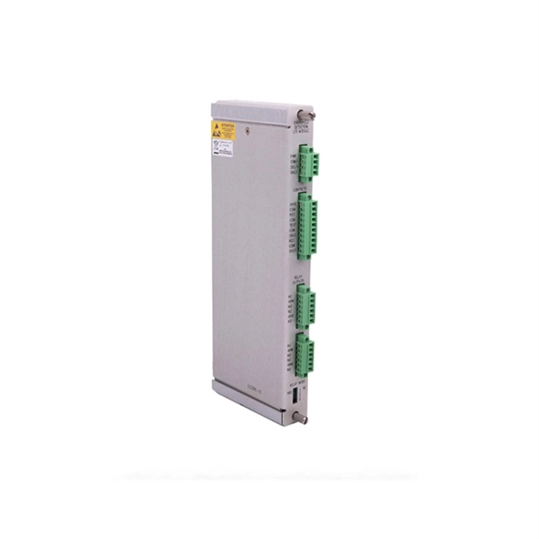
Learn how to monitor SFP optical power on Cisco switches, interpret Tx/Rx levels, and troubleshoot fiber link issues. Step-by-step CLI commands, model-specific guidance, and best practices included. In this article, we will break down the key factors influencing TX/RX power, explain how to calculate the optical power budget, and provide actionable insights for optimizing your network's performance using SFP modules. SFP (Small Form-Factor Pluggable) modules are compact transceivers that allow. SFP (Small Form-factor Pluggable) optical modules are compact, hot-pluggable transceivers that enable network equipment to connect seamlessly to fiber and copper links. Even if an interface appears up, degraded Tx/Rx levels can cause intermittent flapping, packet loss, or err-disabled states. Think of it as the “translator” for your network equipment, converting electrical signals into optical signals. The most two important factors of the SFP transceiver: Output power (TX power) and receiver sensitivity (RX sensitivity). The optical TX power is the signal level leaving from that device, which should be within the transmitter power range. The RX sensitivity is the incoming signal level being. In current network communication, SFP optical modules are an indispensable physical foundation for building network channels. They form high-speed channels for optical signal transmission. Therefore, to ensure their.
[PDF]

Traditional pluggable optical modules are approaching their physical limits in three core dimensions: power consumption control, signal integrity and port bandwidth density. Low Latency: LPO technology eliminates the need for a DSP, reducing a processing step and thus lowering data transmission latency. This advantage is particularly important in high-performance computing (HPC) scenarios, where minimizing latency is a key factor in achieving optimal performance. By. Among the emerging technologies, LPO (Linear Pluggable Optics), NPO (Near-Packaged Optics), and CPO (Co-Packaged Optics) represent three important stages in the evolution of next-generation data center optical networking. Understanding how these architectures differ is essential for designing. Optical communications are emerging as the next AI computing infrastructure frontier, driven by data interconnection bottlenecks. Lumentum's order book is full through 2028, reflecting surging demand for 800G and 1. 6T optical modules, amplified by Nvidia's strategic investment., May 4, 2026 – GlobalFoundries (Nasdaq: GFS) (GF) today announced the introduction of its SCALE™ optical module solution for co-packaged optics (CPO). GF's SCALE. In Feb. 2023, the State Council issued the "Overall Layout Plan for Digital China Construction. ” It proposes six key tasks,including enhancing the efficient.
[PDF]

By operating from a single 2. 5V input power rail and integrating the controller, gate driver, power inductor, and MOSFETs, these mini modules are optimized for space-constrained applications like optical modules, wearables, IoT, networking. SFP (Small Form-factor Pluggable) optical modules are compact, hot-pluggable transceivers that enable network equipment to connect seamlessly to fiber and copper links. These modules, including SFP, SFP+, and SFP28, are widely used in enterprise networks, data centers, and carrier-grade deployments. The optical module serves as a crucial component in optical fiber communication systems, operating at the physical layer, which is the lowest layer in the OSI model. Its primary function is to achieve optoelectronic conversion by converting electrical signals into optical signals and vice versa. Think of it as the “translator” for your network equipment, converting electrical signals into optical signals. As an essential component of optical fiber communication, optical modules are optoelectronic devices that facilitate the conversion between optical and electrical signals during the transmission process. They are essential in applications like telecommunications, data centers, and enterprise networks. Optoelectronic devices have transmitting and receiving modes.
[PDF]
Explore 20 top manufacturers and suppliers of Optical Time-Domain Reflectometers in our comprehensive photonics buyers' guide. Importer and distributor of photonics components and subsystems for use in instrumentation. Optical time-domain reflectometers (OTDRs) are measurement instruments that inject optical pulses into a fiber and measure the returning light scattered by Rayleigh scattering or reflected by Fresnel reflections. Products include photomultiplier tubes, solid-state photodetectors, IR. Time-Domain Reflectometers (TDR) and Optical Time-Domain Reflectometers (OTDR) are essential tools used in telecommunications, fiber optics, and cable testing industries for analyzing the integrity of cables and pinpointing faults. Various time-domain reflectometers are available, intended for different uses and requirements. These are some of the reflections using a comparative TDR. Our catalog includes 106,303 manufacturers, 20,788 distributors and 94,584 service providers.
[PDF]
By studying the expansion of Chinese telecommunications companies abroad, with a particular focus on Africa in our case study, the chapter aims to explore the relationship (i. partnership or/and competition) between African and Chinese telecommunications in. Chinese telecom infrastructure in Africa has expanded rapidly, embedding Beijing's influence into the continent's digital backbone. Upholding the principles of sincerity, real results, amity and good faith, China and African countries have achieved notable outcomes in infrastructure cooperation. Africa is China's. Chinese involvement in Africa's telecoms sector predates the DSR. The global advance of Chinese telecommunications firms, such as Huawei and Zhongxing Telecom Ltd (ZTE), was largely enabled by China's “go out policy,” which was launched in 1999 with the aim of promoting the internationalization of. According to the Tech Review Africa and Chinese Xinhua News, China Mobile officially activated 2Africa East Segment Submarine Cable on November 7, 2025, with an aim to power digital transformation across the African continent. The 2Africa submarine cable system, which spans 33 countries across. Infrastructure cooperation between China and Africa is thriving, and the outcome is changing the lives of millions. Industrial leaders and officials observed that the infrastructure projects undertaken by Chinese companies have yielded tangible benefits for Africans, helping the continent enhance.
[PDF]

It consists of 5 buttons. A power button, a button to turn on the VFL, a lambda button to set the wavelendth, a REF button, and a dBm/W button to set the unit of power. First, you check the initial power of a light signal. Then you check its power at the other end of optical. OPM interface: insert the fiber to be tested, test the optical power. REF/dB key: Short press the dB to switch unit, click once nW/dBm/dB to enter the upper clear data, press and hold until REF is displayed on the screen, and set the current optical power as reference value, enter the relative. There are two buttons on this meter. One is the power button, used to turn the meter on/off. At the top, there is a sensor that detects the light beam. The. at -22 (or 25 with tone on)). To do this you. Active Equipment Power Measurement Fiber Continuity Patch Cable Testing Check MM Reference Cables - Dual OWL MM Sources Check MM Reference Cables - WaveSource MM Sources Check SM Reference Cables - Laser OWL SM Sources Check SM Reference Cables - WaveSource SM Sources. Power-off: Press and hold “MODE” key for 2 seconds or more until “OFF” displays on the screen. Note: This instrument will shut down automatically without receiving any operation instruction for 10 minutes. Function selections: It.
[PDF]

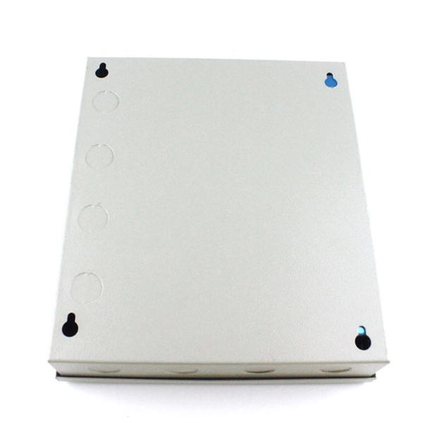
We provide high-quality products including electrical plugs, cables, switches, solar systems, and power distribution components that meet international standards. Delivering advanced high & low voltage switchgear, distribution cabinets and energy storage solutions to power Iraq's industrial and infrastructure growth Certified, field-proven switchgear and distribution cabinets engineered to meet Iraq's demanding industrial environments Understanding the. In the realm of electrical equipment and supplies, iraq electrical cabinet play a crucial role in protecting sensitive electronics and instruments. These enclosures are designed to house and safeguard electronic components from environmental factors such as dust, moisture, and physical damage. ALMUSSAIB Unit 3 Major Turbine Generator & amp, Bop Rehabilitation. Amman Technology Company was established in Amman /Jordan in 2005. ALRASIKH and ALMERJAL are two Iraqi companies specialized in Power Generation, Power Distribution, Oil and Gas Industry. Your application has been sent. Al Ebtida is an Iraqi company specialized in supplying power distribution products & systems to the Iraqi market. We established long term partnerships with international manufacturers in order to supply your projects with high quality & reliable products.
[PDF]

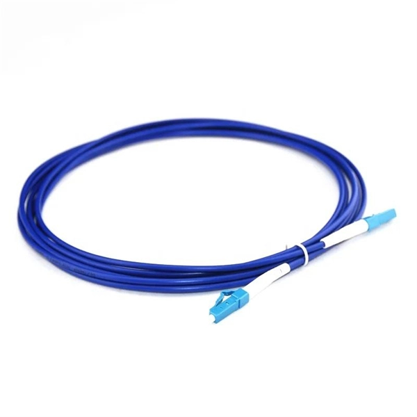
Instead of relying on assumptions, this guide offers a clear-eyed look at how to properly secure your fiber infrastructure, moving beyond the myths to implement practical, layered defenses that provide real-world protection for your organization's most sensitive data. For manufacturers and industry professionals involved in creating, deploying, or maintaining these critical systems, ensuring the robust and reliable securement of fiber optic cables is paramount. “Securing” fiber optic cable goes beyond just preventing it from moving; it encompasses protecting its. Fiber optic cables enable high-speed, long-distance data transfer, forming the backbone of modern communication. Yet, outdoors, they face temperature swings, moisture, UV exposure, rodents, and human interference. Protecting them is essential for long-term reliability. This guide covers how to. Fiber optic and ACSR (Aluminum Conductor Steel Reinforced) cables play a critical role in modern infrastructure, including power transmission and telecommunications. However, these cables face several challenges that can compromise their performance and longevity. If you are an optical engineer or a fiber optic network operator, you need to know how to protect your cables from these threats and ensure. An effective fiber optic network security plan acknowledges these potential weak spots and addresses them head-on. Before beginning any installation, safety.
[PDF]
Armenia operates one Soviet-designed VVER-440 nuclear unit at Metsamor, which supplies over 40% of the country's energy needs. The EU and Turkey have expressed concern about the continuing operation of the plant.OverviewThe electricity sector of includes several companies engaged in electricity generation and distribution. Generation is. According to in 2015 electricity generation in Armenia increased since 2009 to nearly 8000 GWh, but still remains below 1990 levels. Also, in 2015 Armenia consumed more than twice as much na. Nuclear power provides 38% of the electricity in Armenia through one operating nuclear reactor, Unit 2 of, which is a reactor with extra seismic reinforcement. It was created in 1. During 2010–2017 thermal power plants (running on imported natural gas from Russia and Iran) provided about one-third of Armenia's electricity. Thermal power plants (running on natural gas) in Arm. According to total final consumption of electric energy in 2016 amounted to 458.2 ktoe and was broken down as presented on the graph to the right. In 2014, Armenia consumed 5352 GWh of the total 79. Distribution is controlled by Electric Networks of Armenia (ENA), High Voltage Electrical Networks, and Electro Power System Operator. There are over 36,000 km of distribution lines across Armenia. In 2002, El. For three kilowatt hours of electricity Iran pays a cubic metre of gas. Electricity supplier prices are determined by the Settlement Center of.
[PDF]
Here you can download the program for the configuration of our electrical cabinets. Written by Schneider Electric's most talented electrical distribution experts, the Electrical Installation Guide is written for professionals who design, install, inspect, and maintain low-voltage electrical installations in compliance with the standards published by the International. Perhaps you need to minimise heat losses to air in a facility without air-conditioning? Many of our most popular DC and AC power systems can be built into IP54 cabinets. An IP54 level of Ingress Protection provides a high level of protection against non-conductive airborne pollutants. Used to house electrical or electronic switchgear, control gear and equipment. The PDU series is designed to meet the needs of power distribution units of telecom access sites. It comes with an integrated controller that enables customer to read tenant-wise energy statistics as well as to extend the remote monitoring access. It is flexible enough to mount in the different. This Electrical Installation Wiki is a collaborative platform, brought to you by Schneider Electric: our experts are continuously improving its content, collaboration is also open to all. DC power is typically used in Data Centres and telecom facilities as it has several benefits. Firstly, DC power can be more efficient than AC power systems as the need for AC to DC conversion is.
[PDF]

This article will introduce passive optical networks (PON), in which we will introduce everything about OLTs, ONTs, ONUs, and ODNs, including their operation principles and functions. PON (Passive Optical Network) refers to a fiber optic network built using a point-to-multipoint topology and fiber. Active Optical Networks (AON) and Passive Optical Networks (PON) make FTTH broadband connections possible. To date, most FTTH deployments in planning and deployment have used PON to save on fiber costs. PON has attracted much attention in recent years due to its low cost and high performance. There are no specific requirements for this document. This document is not restricted to specific software and hardware versions. The information in this document was created from the devices in a. OLT, ONU, ONT, and ODN are key components and acronyms used in Passive Optical Network (PON) architecture, which is a popular technology for delivering high-speed broadband services. This technology is widely used in fiber-to-the-home (FTTH) and fiber-to-the-premises (FTTP) deployments. In contrast to AON, multiple customers are connected to a single transceiver by means of. An Optical Distribution Network (ODN) serves as the bridge in a Passive Optical Network (PON), transmitting optical signals from the Optical Line Terminal (OLT) to the Optical Network Unit or Terminal (ONU/ONT), thus linking a service provider's core network to end-users (residential or business).
[PDF]

CIF Incoterms is one of the most commonly used terms in international trade transport. Having a deep understanding of its meaning, usage scenarios, price calculations, and other aspects can be extremely helpful for practical trade. Below is a detailed introduction to CIF. Search from Thousands of Senegal Tenders, Bids, EOIs and RFPs. You are Successfully Registered to SenegalTenders!! Recruitment of a service provider for the organization of a holiday camp for the benefit of the children of personnel of the Société Africaine de Raffinage (SAR). The service provider. Cost, Insurance and Freight (CIF) is an Incoterm rule that is identical to the CFR Incoterm rule except in one aspect: insurance. Even though the risk transfers to the seller upon loading the goods on board the vessel, in CIF, the seller is obliged to take out insurance cover for the buyer's risk. This term not only determines the total cost of goods but also impacts decisions related to logistics, pricing, and risk management. In this guide, we'll break down what CIF means, how it's calculated, and. Subscribe to get Senegal government tenders, Bids, RFPs and eProcurement notices from the biggest online database of Senegal. We suggest you read it.
[PDF]

In this complete wiring diagram guide, we will walk you through the step-by-step process of wiring a mag starter. We will explain the purpose and function of each component, provide clear diagrams, and offer expert tips to ensure a successful installation. Whether you're a beginner or an. For proper integration of an electromagnetic securing device, ensure the power supply matches the specified voltage–typically 12V or 24V DC. Incorrect voltage can cause malfunction or reduced holding force. Use a regulated power source to prevent current fluctuations that might trigger false alarms. Understanding the wiring diagram of a magnetic starter is essential for technicians and electricians who work with electric motors. This diagram provides a visual representation of the components and connections involved in the operation of the starter. Once you have everything ready, you can proceed with the installation process. Begin by determining the appropriate position for the magnetic lock on the door. Quick guide on how to wire an access control system with power supply, lock, and exit button. more Quick guide on how to wire an access control. Installing a magnetic door lock can be a cost-effective and reliable way to secure your doors. These locks use an electromagnetic current to keep the door securely closed, and they are commonly used in commercial and residential buildings.
[PDF]
From the transformer, power goes to the busbar that can split the distribution power off in multiple directions. The bus distributes power to distribution lines, which fan out to customers.OverviewElectric power distribution is the final stage in the. Electricity is carried from the to individual consumers. Distribution connect to the transmission system an. Electric power distribution become necessary only in the 1880s, when electricity started being generated at. Until then, electricity was usually generated where it was used. The first power-distri. Electric power begins at a generating station, where the potential difference can be as high as 33,000 volts. AC is usually used. Users of large amounts of DC power such as some,. Primary distribution voltages range from 4 kV to 35 kV phase-to-phase (2.4 kV to 20 kV phase-to-neutral) Only large consumers are fed directly from distribution voltages; most utility customers are connected to a transformer.
[PDF]

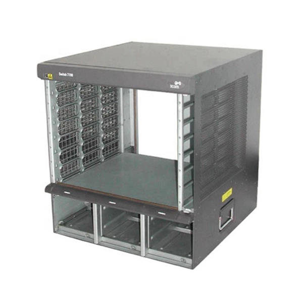
Here's a list of the best Routers for Enterprise. Filter the results based on user ratings, pricing, features, platform, region, support, and other criteria to find the best option for you. 1. Full-service routers designed to serve as enterprise WAN core nodes, large enterprise network access nodes, DCI nodes, and campus or large-scale IDC network egress. Optical networking equipment includes fiber optic cables, transceivers, switches, and routers. The market is driven by the. Our Engineers take a hands-on approach to replicating networks, maintaining reliability and providing the highest level of service. Wi-Fi 6 (802. 11ax) indoor wireless access point Dual-radio, dual-band Up to. Desktop All-in-One enterprise-class wireless router Including 5 Gigabit ethernet ports. Reyee 10-Port Gigabit Cloud Managed Router 10-Port Gigabit Cloud Managed. Reyee 10-Port Gigabit Cloud Managed PoE Router 10-Port. Future-proof your network with our full-stack offer. Get started with the right security solution for you. See more, move faster, go farther. Human. To provide secure, reliable affordable and high quality converged telecommunication services anytime, anywhere for an accelerated inclusive socio-economic development. To develop a robust and secure state-of-the-art telecommunication network providing seamless coverage with special focus on rural.
[PDF]