The development of the relay protection based on open architecture is a relevant direction of electrical and electronic engineering. The paper presents the problem of the modern microprocessor-based relay prote.
[PDF]

Cable trays play a key part in keeping fire protection systems working. Here is what they do: They Make Safe Paths for Fire System Wires Cable trays are made from materials that resist fire. They can help stop fire from spreading. Recognize electrical cable tray misuse that can lead to electric shock and arc-flash/blast events and fires caused by overheating. The use and installation of cable trays is covered by legally enforceable OSHA regulations in 29 CFR 1910. 305(a)(3), or comparable standards promulgated by States. Scope: Firestopping for busway, cable trays, cables, and trunking passing through walls in enclosed electrical installations. Where cables pass through shafts, walls, slabs, or enter electrical panels or cabinets, openings shall be tightly sealed with firestopping materials in accordance with. Cable trays can be part of a planned cable management system to support, route, protect, and provide a pathway for cable systems. Power, low voltage control, data, or telecommunications wiring distribution systems can be used with cable trays. 1 This section applies to cable trays utilized to support and route low voltage cables (telecom, security, A/V). No fire alarm cables will be permitted to be installed in cable trays. If a fire starts, the tray protects the wires inside from flames and.
[PDF]

Their core functions can be summarized as: enabling efficient cable branching, safe isolation, flexible control, and reliable protection of cable lines, thereby improving the reliability, flexibility, and maintainability of the power distribution network. A distribution box, often simply called a DB, is a crucial component in any electrical installation. Think of it as the heart of your building's electrical system. Just as a heart receives blood and pumps it to various parts of the body, the distribution box receives the main electrical supply and. Safety protection function in low voltage distribution boxes prevents electrical hazards and ensures reliable, secure power distribution for your operations. You rely on the safety protection function of a low voltage distribution box every day. These safety protection function features guard you. A distribution boxes is an essential device that safely and efficiently distributes electrical power to different areas within a building or facility. It is commonly used in homes, businesses, and industrial settings to control and protect electrical circuits. Today, electrical systems are essential for homes and industries. Understanding its significance.
[PDF]

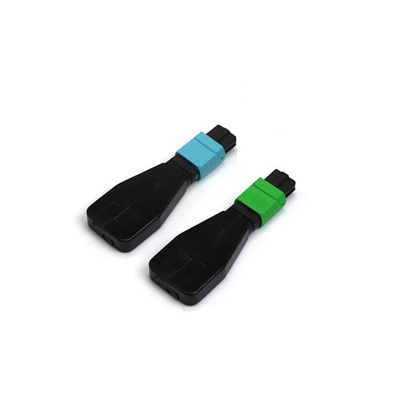
FS optical line protection switch features 1+1 backup and less than 15 ms fast switch to the standby fiber link that ensures business uninterrupted when malfunction occurs. An optical protection switch is a critical component in fiber optic communication systems designed to safeguard optical signals and infrastructure from damage due to power surges, signal overloads, or system failures. These switches ensure signal integrity, minimize downtime, and enhance network. 1+1 Optical Line Protection System for Fiber Protection, Bi-directional Protection in Dual Fiber, LC/UPC, Pluggable Module OLP (Optical Line Protection) is a device used in pairs, one at each end of the optical signal to protect network transmission line. OLP products include fiber optical line protection switches, optical bypass switches, optical cross connection, multi-channel. The FOSW-1x1 or 1x2 optical switch is based on opto-mechanical technology with proven reliability. OSW-W1x2 optical switch is a high performance electro-optical device, with low insertion loss (typic. In optical communication network, OLP monitors optical power of optical fiber and standby.
[PDF]
AFL Mexico and South America offers fiber optic cable, transmission and substation accessories, outside plant equipment, connectors, fusion splicers, test and inspection equipment. Identify and compare relevant B2B manufacturers, suppliers and retailers Max. The company offers training in real-world scenarios with experts, both virtually and in-person, focusing on fiber optic installation and network design. They provide certification and have expertise in optical splicing. [June 12, 2024 – Guadalajara, Mexico] Test Research, Inc. (TRI), the leading Test and Inspection systems provider for the electronics manufacturing industry, recently opened a new office in Guadalajara, Mexico, to accommodate the industry's rapid growth. TRI's expansion in Mexico emphasizes its. On August 8th, operations commenced at Yangtze Optics Mexico Cable S. in Mexico's Jalisco State, marking the establishment of Yangtze Optical Fibre and Cable Joint Stock Limited Company's (YOFC) first production facility in the nation. This development not only represents a significant. Minqing Fibramerica Technology, under its trade name FIBRAMÉRICA, is one of the world's leading companies dedicated to the design, development, manufacture, distribution and marketing of advanced optical connectivity solutions. We work closely with the main players in the telecommunications market.
[PDF]
GPON Xpert is a modular tool designed for R&D, laboratory and field application engineers engaged in the development, testing and deployment of G-PON standard-compliant solutions. The GPON Xpert multi-layer analyzer is a unique protocol analyzer for G-PON products. GPON Xpert verifies the. Fiber Optical Test offers a comprehensive line of PON-specific testing solutions designed for fiber network installation, activation, and maintenance. Passive Optical Networks (PON) demand precise testing technologies tailored to their unique architecture and performance requirements. Fiber Optical. OLP-88 TruePON tester is an innovative tool using GPON data analysis technology. It is the ideal test unit for field technicians dealing with GPON network service activation and for support teams in charge of resolving service complaints and identifying the sources of issues. GPON Xpert verifies the. TraceSpan's non-intrusive solutions empower broadband access networking with deep protocol analysis across all communication layers Gain complete visibility and deep understanding of your access network elements and the traffic running through them, powered by independent testing tools and.
[PDF]

Run the loopback-detect untagged mac-address ffff-ffff-ffff command in the system view to broadcast BPDUs for loopback detection and prevent them from being terminated by unexpected devices. Huawei's comprehensive portfolio of products and solutions enables you to realize smooth digital transformation and rapid growth of virtualization, Big Data, and cloud services. Huawei switches already help customers achieve success in industries such as finance, Internet, retail, education. Plan the network configurations, configure loop prevention protocols, and enable loopback detection to prevent loops. They provide ultra-high-density 10GE/40GE/100GE/200GE/400GE full-rate access ports, meeting customers' requirements for quickly building campus networks with a simplified. CloudEngine S12700H series switches are Huawei's next-generation modular core/aggregation switches designed for high-end campus networks in the all-wireless era of Wi-Fi 6/7. CloudEngine S12700H series switches come in two models, which offer four and eight LPU slots, respectively. The S9700 uses an advanced multilayer switching architecture to support sustained bandwidth upgrading and to provide 40GE. This document provides campus networks typical configuration examples and feature typical configuration examples. "Campus Networks Typical Configuration Examples" provides typical campus network networking modes and a variety of deployment examples.
[PDF]
United Rentals has low-pressure air testing equipment for rent, most commonly used to test for line acceptance or leaks in pipe joints and sewer line installation. For more. Air Testers install blower door testing equipment (big fans) to an external opening (typically a doorway) and will use this to pressurise or depressurises the building and test over pressure differentials Using thermal imaging, the tester will be able to identify air leakage points where warm air. Simple to Operate: The air ejector has no moving parts and no lubrication is necessary. After applying leak detection fluid along the seam, simply place the vacuum device over the area to be detected and open the air valve. Rugged Yet Lightweight: Our shockproof Vacuum Devices are built with. A pioneering approach to fabric air permeability measurement that releases a low-pressure pulse of air for realistic and accurate measurement of airtightness of buildings in seconds. A portable diagnostics fan that can help identify air leakage paths within buildings, helping to minimise. This is where you can browse products in this store. For more information, visit our resource. Airtightness tester s help make homes use less electricity by finding where air leaks are. When structures are less leaky, they need lower utility bills to heat or cool them. This savings makes buildings more environmentally friendly. By sealing tightly, pollution from outside cannot easily enter.
[PDF]
The ASTM D6344 standard is intended to evaluate the ability of packaging to resist the force of concentrated impacts from outside sources, such as those encountered in various modes of transportation and handling. Damage to enclosures can impair the function of the equipment installed within (e. the con-trol systems of machines) or even, in the worst case, render it non-functional. Accordingly, in addition to IP protection (protection against dust, contact and water), enclosures must also have an adequate. 4. This test method is intended to determine the ability of packaging to protect. The first digit is our shield against these invaders: IP5X (Level 5): Dust-resistant—keeps out most particles but not completely dust-tight. Perfect for urban events or lightly dusty areas. IP6X (Level 6): Dust-tight—absolute protection against fine powders and particles. Essential for quarries or. Please review the permitted and restricted actions below: Standard Test Method for Concentrated Impacts to Transport Packages 1. 1 This test method covers procedures and equipment for testing complete filled transport packages for resistance against concentrated low-level impacts typical of those.
[PDF]
In electric power systems and industrial automation, ANSI Device Numbers can be used to identify equipment and devices in a system such as relays, circuit breakers, or instruments. The device numbers are enumerated in ANSI/IEEE Standard C37.2 Standard for Electrical Power System Device Function Numbers, Acronyms, and Contact Designations. Many of these devices protect electrical. List of device numbers and acronyms• 1 - Master Element• 2 - Time-delay Starting or Closing Relay• 3 - Checking or Interlocking Relay, complete Sequence• 4 - Master Protective. A suffix letter or number may be used with the device number; for example, suffix N is used if the device is connected to a Neutral wire (example: 59N in a relay is used for protection against Neutral Displacement); and suffixe.
[PDF]

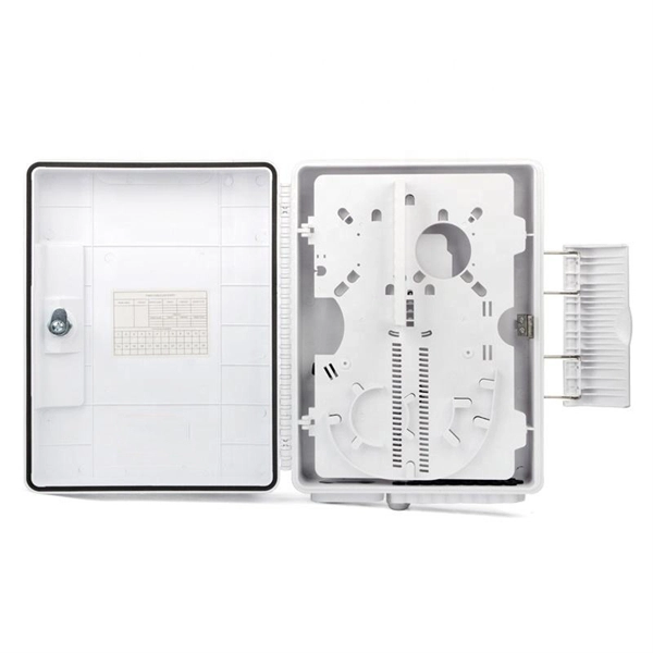
Protect fiber optic cable connections:The joint box provides physical protection for the fiber optic cable connection parts to prevent damage to the fiber optic cable caused by external environmental factors such as moisture, dust, chemical corrosion and mechanical damage. Provide a stable. Fiber optic sleeves are protective devices used for fiber optic connections. Splice protection sleeve, usually made of plastic or metal, are used to secure and protect the fusion joint between two optical fibers. Fiber Cable Joint Box is attributed to the mechanical pressure sealing joint system. Fiber Cable Joint Box is a continuous protection device for supplying optical, sealing and mechanical strength continuity between adjacent optical. The optical fiber terminal box is the terminal joint of an optical cable, one end of which is an optical cable, and the other end is a pigtail, which is equivalent to a device that splits an optical cable into a single optical fiber. The user optical cable terminal box installed on the wall, its. Fiber Optic Splice Closure is designed to protect optical fibers from debris, dirt, dust, moisture and water. As much of the fiber system is outside in a harsh environment, these fiber optic splice closures are designed to meet the tough protection requirements of fiber-optic splices. UnitekFiber. Overview Application of Optical Fiber Splice Closure/Joint Box/Joint Closure: 1. CATV environment.
[PDF]

The International Protection (IP) rating system defines minimum requirements for water and dust ingress protection, with outdoor applications typically requiring IP65 or higher ratings. Weatherproof outdoor distribution boxes ensure reliable power distribution in challenging environments by protecting against moisture, dust, and temperature extremes. Key design points include high-quality materials like ABS plastic, aluminum, and stainless steel that resist corrosion and UV. (1) Waterproof distribution box engineered for harsh outdoor and industrial environments, providing IP65–IP68 sealing against dust, rain, and UV. Beyond preventing acute water damage, these enclosures also protect against humidity-related. Yet one factor often overlooked is how well electrical components are protected from dust and moisture. That's where Ingress Protection (IP) ratings come in. If you've ever bought a weatherproof junction box or a distribution enclosure, you've probably noticed codes like IP65, IP67, or IP68 printed. Low voltage distribution box outdoor use requires IP65 or NEMA 4X ratings, corrosion-resistant materials, and proper sealing for lasting weather protection. You use a low voltage distribution box to keep electrical systems safe outside. Let's take a closer look at NEMA ratings and other weatherproofing considerations for.
[PDF]
Important transmission lines and generators have cubicles dedicated to protection, with many individual electromechanical devices, or one or two microprocessor relays.OverviewIn, a protective relay is a device designed to trip a when a is detected. The first protective relays were electromagnetic devices, relying on coils operating on moving par. Electromechanical protective relays operate by either, or. Unlike switching type electromechanical with fixed and usually ill-defined operating voltage thresholds.
[PDF]

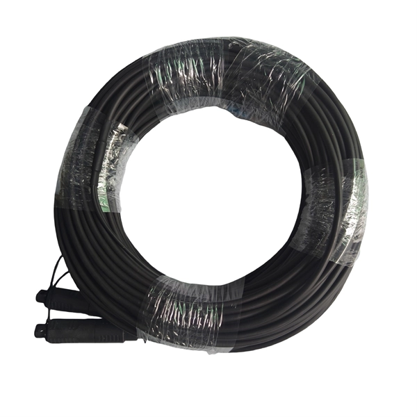
The National Electrical Code (NEC) has established eight levels of fire resistance for fiber optic cables. These levels are based on the time it takes for a cable to burn through or melt. Corning Optical Communications manufactures quality flame retardant optical fiber cables for indoor applications, which comply with the requirements of the National Electric Code® (NEC® 2023) published by the National Fire Protection Agency (NFPA). To ensure compliance to these requirements, a. Understanding the listing requirements of fire alarm circuit cables can help you make sense of the cable alphabet soup. Here are some highlights from Part IV of Article 770. There's plenty of "expansion room" built into Article 770. Part I ends with Section 770. 44. Cabling Installation & Maintenance - Classes 1, 2, 3, and 4, communications, fire alarm, and optical fiber cables are all addressed in the NEC. By Stanley Kaufman, PhD, CableSafe Inc. UL Solutions' long-standing history in certification and Standards development makes us a trusted thought leader in the. Understanding the fire ratings and jacket options for fiber optic cables is crucial for ensuring optimal performance and safety. This technical guide will provide a comprehensive overview of these factors, their implications on cable resilience and transmission, and tips for making informed.
[PDF]

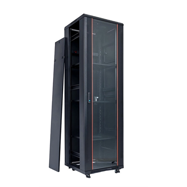
Arduino Safety Relay Box With Wall Socket : A relay is an electrically operated switch. In this project there is no real need to isolate one circuit. Relay rooms are essential in modern commercial or industrial buildings, serving as secure enclosures for electrical relays that manage power distribution and automation systems. Designing a relay room requires balancing technical precision with safety, efficiency, and future scalability. Many relays use an electromagnet to mechanically operate the switch and provide electrical isolation between two circuits. In this article, you will learn how to design an electrical control cabinet for optimal safety and efficiency, following some. This handbook covers the code of practice in protection circuitry including standard lead and device numbers, mode of connections at terminal strips, colour codes in multicore cables, dos and donts in execution. Reliable components ensure system faultlessness and durability. Modern design and user-friendliness. equipment of most. This is Part 1 in a series of tutorials that will show you how to build a Bussmann RTMR fuse/relay block. If you're not familiar with this product, it's a simple waterproof enclosure that allows you to connect accessories on your vehicle through relays and/or fuses. After reading this tutorial, you.
[PDF]


