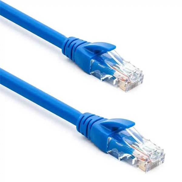
Multi-mode fiber optic patch cords utilize a larger core size, typically around 50-100 microns, allowing them to carry multiple modes of light. This design enables the transmission of data over relatively short distances with high bandwidth capabilities. A fiber-optic patch cord is a fiber-optic cable capped at each end with connectors that allow it to be rapidly and conveniently connected to telecommunication equipment. This is known as interconnect-style cabling. A fiber-optic patch cord is constructed from a core with a high refractive. These short fiber optic cords connect transceivers, switches, patch panels, and servers. Without them, even the best optical modules and switches cannot deliver performance. As data rates increase from 10G → 100G → 400G → 800G, patch cables must handle more bandwidth, more density, and stricter. Fiber optic patch cords, also known as fiber optic patch cables or fiber jumpers, are indispensable components in modern optical networks. They act as the critical link for interconnecting devices like optical switches, servers, and distribution frames. Understanding the various technical. Fiber patch cables, also called fiber-optic patch cords, are cables typically containing one or two optical fibers, which are equipped with standardized fiber connectors on both ends. The function of the fiber patch cord.
[PDF]

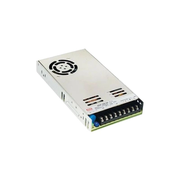
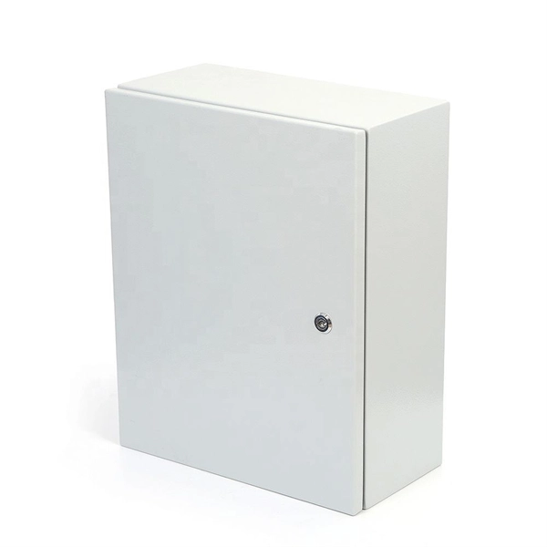
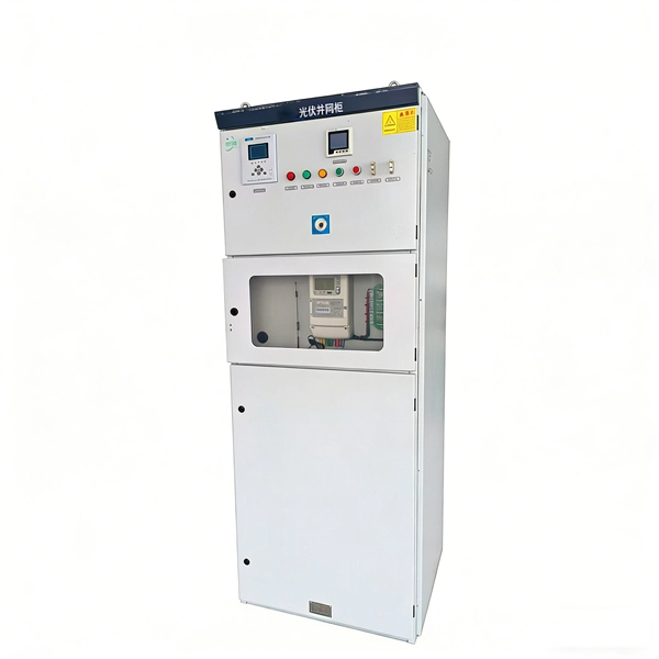
It connects to two independent power sources, enabling automatic switching to a secondary source during primary source failures. This seamless transition prevents disruptions to connected devices and enhances operational reliability. A dual power switching box is precisely the kind of gadget that guarantees a constant flow of electricity as it enables the user to shift the operational state between two different energy supplies. It can be found in homes, workplaces, factories, and anywhere else where sudden cuts of energy can. The ATS Dual Power Distribution Box plays a pivotal role in providing efficient low-voltage power solutions, ensuring that power flows seamlessly, even in the event of an outage. This comprehensive guide offers insights into the mechanisms and benefits of the ATS Dual Power Distribution Box. Transfer switches and sub panel boxes are key components in dual power switching cabinets. Transfer switches automatically switch between power sources during outages, ensuring uninterrupted power and system reliability. This redundancy ensures that if one power source fails, the other can immediately take over, minimizing downtime and preventing. A dual power switch helps you manage two power sources for one system. You can use it to keep your equipment working if the main power stops. This device quickly changes from the main supply to a backup source. This seamless transition.
[PDF]

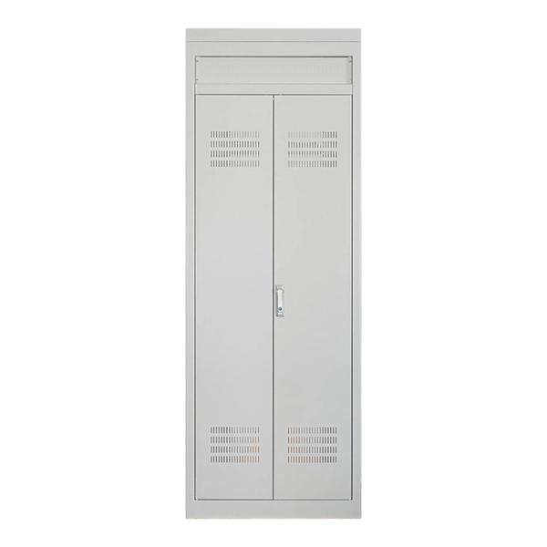
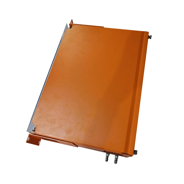
At its core, a fiber termination box combines hardware and software components to facilitate fiber optic connections. The hardware includes protective enclosures, splice trays, adapters, connectors, and patch panels. A Fiber Terminal Box (FTB) is a customer-side termination and distribution device used at the end of the optical network. It is small, so it is considered a mini version of the optical distribution frame or optical distribution frame (ODF). The number of ports of fiber optic junction boxes ranges from 8. A fiber optic junction box, also known as a fiber optic distribution box or termination box, is a protective enclosure that facilitates the connection and management of fiber optic cables. It serves as a central point for organizing and distributing optical fibers, ensuring efficient connectivity. Fiber termination boxes are essential components in modern telecommunications infrastructure. They serve as the critical junction points where fiber optic cables connect, splice, and distribute data signals efficiently and securely. Here's a structured breakdown. This article provides an in-depth comparison of fiber terminal boxes and junction boxes to help clarify their differences and deepen your understanding.
[PDF]

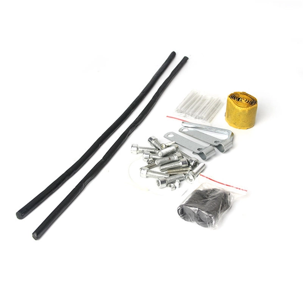
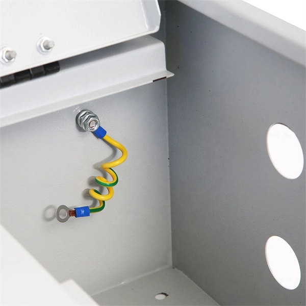
A typical fiber optic splice enclosure consists of several key components that work together to protect and organize the fiber splices. Standard enclosures contain: 1) Housing, 2) Cable fixation clamps, 3) Splice trays, 4) Sealing system. A splice box (also known as splice distributor) is a housing in which fiber optic cables begin or end. Fiber optics are fanned out in splice boxes that are situated at the end of fiber optic transmission paths. Optical cable joint box The optical cable joint box permanently connects two optical cables together and has a joint part for protecting components. The optical cable connection part, that is, the optical cable joint, is the part where the. An optical cable split fiber box, also known as a fiber distribution box or fiber optic splice closure, is a device used to terminate, splice, and distribute optical fibers. In this response, we will focus on the. This guide optimizes the original text by delving deeper into the three pillars of fiber network longevity: the impact of splicing technology, the strategic selection of splice boxes, and the essential maintenance protocols needed to ensure sustained, high-speed functionality. Fibre optic cables are manufactured in standardized lengths –.
[PDF]
There are connectors designed for single mode and multimode fiber optic cables, which differ in core size, bandwidth, and optimal use cases as explained in this comprehensive guide to fiber optic cable.
[PDF]

The main group of impedance relays is distance protection devices. loss of synchronism protection, loss of excitation protection, or impedance automatics like fault locator. Impedance Relay Definition: An impedance relay, also known as a distance relay, is defined as a device that triggers based on the electrical impedance measured from a fault's location to the relay. Working Principle: The operation of an impedance relay hinges on the balance of voltage-induced. When a system has too many radial lines protection using time delay overcurrent relay becomes impractical. This problem can be solved to an extent by using distance relays. Distance relays uses voltage and current to calculate the. Distance relay protection has been defined as a part of relay protection in power systems that detects and isolates faults based on the distance between the relay and fault points. Unlike overcurrent relays, which only respond to the magnitude of current, a distance relay measures the impedance of. Such relays are called Distance Relays or Impedance Relays. In an impedance relay, the torque produced by a current element is opposed by the torque produced by a voltage element. The relay will operate when the ratio V/I is less than a predetermined value. The voltage transformer measures the voltage across the protected equipment, while the current transformer measures the current flowing through it.
[PDF]
The WannaCry ransomware attack was a worldwide cyberattack in May 2017 by the WannaCry ransomware cryptoworm, which targeted computers running the Microsoft Windows operating system by encrypting data and demanding ransom payments in the form of bitcoin cryptocurrency. It was propagated using EternalBlue, an exploit developed by the United States National Security Agen. DescriptionWannaCry is a , which targets computers running the by encrypting (locking) data and demanding ransom payments in the. The attack began on Friday, 12 May 2017, with evidence pointing to an initial infection in Asia at 07:44 UTC. The initial infection was likely through an exposed SMB port, rather than as initially ass. Linguistic analysis of the ransom notes suggested the authors were likely fluent in Chinese and proficient in English, as the versions of the notes in those languages appeared to be human-written while the rest seeme. The ransomware campaign was unprecedented in scale according to, which estimates that around 200,000 computers were infected across 150 countries. According to, the four mo.
[PDF]
There are two main types of RF attenuators: fixed and variable. Fixed Attenuators: Provide a fixed amount of attenuation, typically designed using discrete or chip resistors. These can be further divided into:. Attenuators are designed to change the magnitude of the input signal seen at the input stage, while presenting a constant impedance on all ranges at the attenuator input. A compensated RC attenuator is required to attenuate all frequencies equally. Without this compensation, HF signal measurements. Let's look at the common types of attenuators Fixed attenuators, as their name suggests, are fixed or unchanging. These are used in applications that don't require changing levels of attenuation or where an occasional replacement of one attenuator with another is acceptable. Say we now add a 6 dB pad between. An RF Attenuator is a two-port passive electronic device designed to reduce (attenuate) the power or amplitude of an RF signal. They can adjust the signal strength by controlling the amount of attenuation, ensuring that the signal reaches the desired level for transmission in a.
[PDF]
Discover the most common types and models of Direct Attach Cables (DACs), including 10G, 25G, 40G, 100G, 200G, and 400G. A Direct Attach Cable (DAC) is a factory-assembled high-speed copper cable with fixed connector “module-style” ends. It's widely used for short-reach links in data centers because it delivers low latency, simple deployment, and cost-efficient interconnects-especially for rack-level connectivity. These cables come pre-terminated with SFP (Small Form-factor Pluggable) or QSFP (Quad Small Form-factor Pluggable) connectors which simplify network setup. High-speed cable is a kind of low-cost short-distance connection solution to replace optical modules. Both of its ends have cable assemblies of a module, which are connected. Direct attach copper (DAC) cables are twinax copper assemblies with fixed transceiver-like ends. They deliver high bandwidth, low latency, and great density for top-of-rack (ToR), server-to-switch and switch-to-switch connections. This article summarizes the common DAC categories and. What is a Direct Attach Copper (DAC) Cable? Common Types And Uses Summary : Direct Attach Copper (DAC) cables provide fast, reliable, and cost-effective short-distance connections for data centers, enterprise networks, and top-of-rack setups. With passive and active variants, DAC cables offer.
[PDF]
Fiber optic couplers can either be passive or active devices. Passivefiber optic couplers are said to be passive as no power is required for operation. They are simple fiber optic components that are used to re.
[PDF]
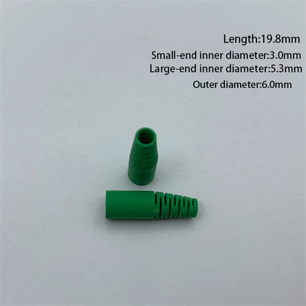
This guide covers everything: what fiber optic pigtails are, how they differ from patch cords, which connector and polish type to specify, how to choose between mechanical and fusion splicing, and the real-world applications where pigtails are the right call. Types and Applications A pigtail connector is a short cable with a connector on one end and bare (stripped) wire or fiber on the other. In fiber optics, pigtails are fusion-spliced to field fiber inside splice trays — the most common termination method in telecom and data center networks. In. Whether it's an electrical system in your car, home, or factory, the quality of the connection is essential, and that's where pigtail connectors come in. These small, often overlooked components ensure a strong, safe electrical connection. It serves as a bridge, allowing technicians to repair specific connection points without disturbing the rest of the system. By the end, you will have a comprehensive understanding of why pigtails deserve a place in every fiber deployment toolkit. People often make this connection in the field, where they must make temporary repairs or. Executive Summary: A fiber optic pigtail is one of the most commonly specified yet least understood components in structured cabling. Get the wrong connector type, the wrong polish, or skip proper fusion splicing technique—and you're looking at elevated signal loss, increased back reflection, and a.
[PDF]
A beam splitter or beamsplitter is an that splits a beam of into a transmitted and a reflected beam. It is a crucial part of many optical experimental and measurement systems, such as, also finding widespread application in.
[PDF]
In fiber optic circuit technology an optical fiber link is used for transferring digital or analogue data in the form light frequency through a cable which has a highly reflective central core. Internally, the optical fiber.
[PDF]
This page describes the structure, working operation, advantages, and disadvantages of a Fiber Bragg Grating (FBG) Sensor. Fiber optic sensors work by modulating one or more properties of the light wave, such as intensity, phase, polarization, and frequency. Fiber Bragg grating (FBG) sensors have emerged as advanced tools for monitoring a wide range of physical parameters in various fields, including structural health, aerospace, biochemical, and environmental applications. This review provides a comprehensive overview of FBG sensor technology. A fiber Bragg grating (FBG) is a type of distributed Bragg reflector constructed in a short segment of optical fiber that reflects particular wavelengths of light and transmits all others. An optical fiber typically consists of a. Abstract: Fiber grating sensors are more stable, more reliable and more accurate than traditional electromechanical sensors in many aspects. It can be used to sense and measure physical quantities such as stress, strain or temperature with high sensitivity and measurement range. In this paper, the. Optical fiber sensors (OFS) appeared just after the invention of the practical optical fiber by Corning Glass Works in 1970, now Corning Incorporated, that produced the first fiber with losses below 20 dB/km. At the beginning of this era, optical devices such as laser, photodetectors and the.
[PDF]
The principle of gap-loss is used in optical attenuators to reduce the optical power level by inserting the device in the fiber path using an inline configuration. Gap-loss attenuators are used to prevent the saturation of the receiver and are placed close to the transmitter. The basic types of optical attenuators are fixed, step-wise variable, and continuously variable. The attenuator circuit will allow a known source of power to be reduced by a predetermined factor, which is usually expressed as decibels. In fiber systems, attenuation is specified in dB (a ratio), while optical power is often given in dBm (absolute power referenced to 1 mW). If a transmitter outputs +3 dBm and. If you are still looking to reduce the signal power of optical fiber links, Optical Attenuators are undoubtedly a good choice and can bring you a good solution. Because the signal power of the optical fiber link is too high, it will cause abnormalities in the optical fiber network, so it is. A Variable Optical Attenuator (VOA) is a controllable device used to reduce the optical power traveling through a fiber or free-space optical path. Unlike a fixed attenuator, which imposes a constant loss, a VOA allows the loss to be adjusted from nearly zero up to tens of decibels. Understanding their principles is essential for their effective application. Optical attenuators work by absorbing or reflecting a portion of the optical signal, thus reducing its.
[PDF]