Locate the breaker panel, which looks like a large metal box mounted on the wall. Open the panel and look for a switch that's facing the opposite direction from the others. Turn the switch to “Off” and then “On. ” Contact an electrician if your breaker keeps tripping. Yes, in most cases, you can safely turn on a circuit breaker yourself, provided it has merely tripped due to an overload or a minor fault. However, if a breaker repeatedly trips or if you suspect a more serious electrical issue, it's crucial to consult a qualified electrician. Dealing with a. This wikiHow article will teach you how to safely find and flip a tripped breaker, restoring your power. Turn the switch to. This guide's handy whether you're looking at a circuit breaker for the first time or an electrical veteran looking for a better way to explain what to do if the breaker trips. Why Do Breakers Trip? Circuit breakers trip when there's too much current (aka “ overcurrent “) on the circuit, and it. To reset a tripped breaker, switch it entirely OFF first, then back to the ON position. You don't need to turn off the main power to reset individual breakers. Continuously identify and. Mr. Electric recommends these steps to restore power safely when your circuit breaker trips. Turn off and unplug devices on the affected circuit.
[PDF]
The following tutorial explains how to wire a 120V single-phase breaker and load points in a residential panel. 120V single-phase circuits are commonly used in homes for lighting and receptacle outlets. Plastic is lighter and good for indoor setups. Choose based on where you'll install the box. Inside the box, you'll find things like circuit breakers, busbars, terminal blocks, and wires. These parts control and distribute the electricity to different circuits safely. Some boxes also include DIN. The electrical service panel, often called a breaker box, acts as the central distribution point for all electricity entering a home. Whether you are an electrical contractor or a construction brigade, knowing how to properly and safely install distribution boxes is the basis of ensuring the safe operation of the entire system. This article details the process of installing them, which helps you comprehend distribution boxes. No description has been added to this video. Enjoy the videos and music you love, upload original content, and share it all with friends, family, and the world on YouTube. Jesse Kuhlman is a Master Electrician and the Owner of Kuhlman Electric based in Massachusetts. Jesse specializes in all aspects of home and residential wiring, troubleshooting, generator installation, and WiFi thermostats. Jesse is also the author of four eBooks on home wiring including.
[PDF]

In the following tutorial, we will show how to wire 120V single-phase and 240V split-phase circuit breakers and loads inside a residential main panel. The figure below shows a typical breaker panel used for 120V and 240V circuits. Messy distribution boxes are dangerous and very hard to fix. You will learn to build a safe, efficient, and professional electrical system today. Circuit breaker wiring configurations involve organizing main switches, busbars. A breaker box, also known as a circuit breaker panel, is an essential component of any electrical system. It is responsible for distributing electricity throughout a building, ensuring that each circuit receives the proper amount of power. To understand how a breaker box works, it is helpful to. Each circuit is protected by a circuit breaker, a safety device that automatically shuts off power if it detects an overload or a fault. If you're looking to replace an old fuse box replacement or upgrade your home's power capacity, you'll be dealing with the load center or service panel. The distinction between 1P and 2P circuit breakers plays a pivotal role in determining the appropriate protection level for various circuits. When installing or troubleshooting a power distribution system, understanding how to correctly connect the main electrical supply to the control panel is crucial.
[PDF]
It can occur due to overloaded circuits, short circuits, or ground faults. Solution: Identify the Cause: Check if the breaker is tripping due to overloading. This often happens when too many devices are plugged into one circuit. Reducing the load on the circuit or redistributing. It's shutting off power because something on that circuit isn't safe. The tripping is a warning signal, not a malfunction. But what's causing it? And more importantly, does it need an expensive fix, or is this something simple? The good news: Most circuit breaker trips have straightforward. The main circuit breaker is designed to protect the electrical system in a building or home from overload and potential fire hazards. There are several reasons why a main circuit. A breaker box acts as the central hub that receives electricity from the utility company and distributes it to various circuits in your home. Homeowners will want to hire an electrician to determine the cause of the frequently tripping circuit breaker. When they start tripping, overheating, or making strange noises, it's more than just an inconvenience - it's your home's cry for help. In this guide, we'll walk through these. If you notice that your circuit breakers are often tripping, don't worry. It's a typical issue. Below, you'll find reasons why this occurs and tips to avoid it moving forward. Get a handle on your circuit breaker problems! Circuit breakers are protection devices for electrical circuits.
[PDF]

This guide shows you how to organize circuit breaker wiring properly. You will learn to build a safe, efficient, and professional electrical system today. Circuit breaker wiring configurations involve organizing main switches, busbars, and branch breakers within a distribution box. Messy distribution boxes are dangerous and very hard to fix. You lower the chance of circuits getting too hot or overloaded when you pick the right box for your needs. When installing or troubleshooting a power distribution system, understanding how to correctly connect the main electrical supply to the control panel is crucial. Professional electrical panel schedule tool for creating detailed load distributions, calculating circuit loads, balancing phases, and ensuring NEC compliance for electrical distribution panels. Panel schedules are essential for electrical system documentation, load analysis, and NEC compliance. Material preparation: Prepare the required circuit breakers, wires, wiring ties and other materials, and ensure that they meet the design drawings and installation requirements. Location determination: Determine the installation position of the circuit breaker according to the position of the. Hey, in this article we are going to see the Single Phase Distribution Box Wiring Diagram and Connection Procedure. And all the switching and protective devices are installed in the.
[PDF]
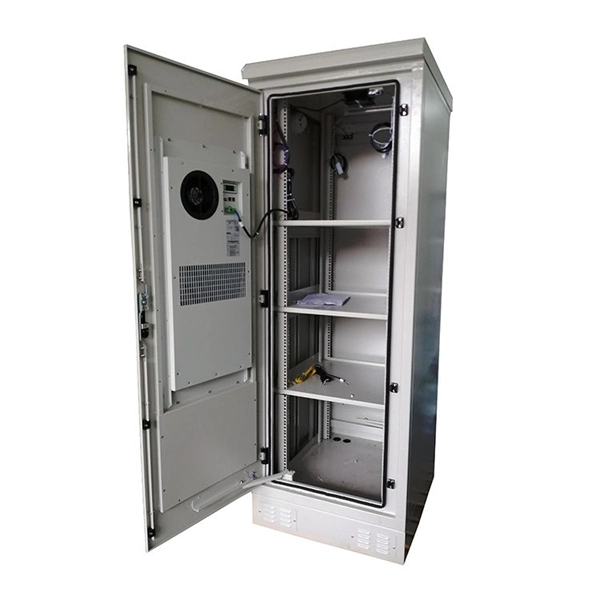
The key lies in their fully sealed design, acting as a “protective shield” for the cabinet, effectively preventing dust, salt spray, and high-temperature air from entering. So, how can this more reliable cooling solution become more economical to support large-scale 5G. ESTEL designs each Telecom Power System and outdoor telecom cabinet to adapt to these challenges. You get reliable performance through robust materials, smart energy management, and advanced engineering. ESTEL's dedication to quality, innovation, and international standards ensures your equipment. With 5G base stations, smart light poles, outdoor communication cabinets and other infrastructures spreading all over urban and rural areas, outdoor telecommunication equipments are facing severe tests such as extreme temperature difference, humidity and rain, and dust intrusion. Traditional. Available in different configurations, Delta OutD cabinets are designed to protect equipment from external threats in all climates from the tropics to the arctic. In addition to traditional cooling methods, Delta's new hybrid cooling options revolutionize the cost structure of thermal management. Featuring a robust steel structure with IP-rated protection, it ensures reliable operation against dust, rain, heat.
[PDF]
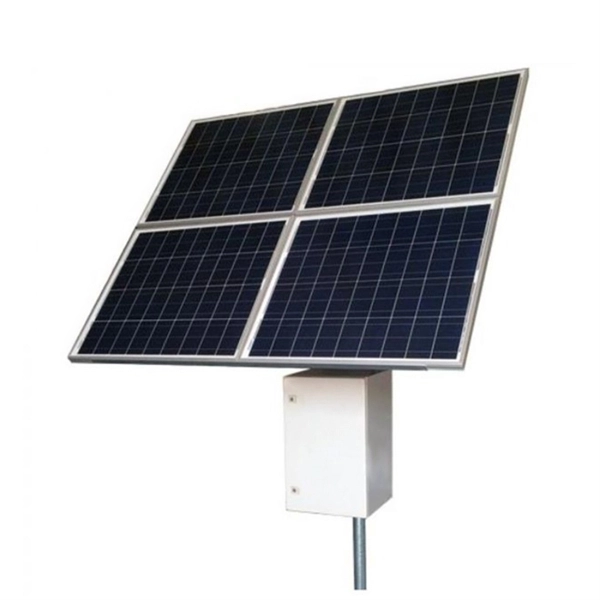
Looking for reliable outdoor power solutions in Casablanca? This guide explores top local suppliers, key features to consider, and emerging trends in Morocco's renewable energy sector. Morocco's ambitious renewable energy targets and growing tourism sector make it a hotspot for outdoor power solutions. With 52% of electricity slated to come from renewables by 2030, businesses and adventurers alike need reliable off-grid systems. Whether you're a homeowner, business operator, or outdoor enthusiast, discover how to find the right power supply. Discover Morocco's top solar energy system suppliers, each pioneering a sustainable future with unique, innovative solar solutions. Morocco, with its abundant sunshine, has embraced solar energy as a cornerstone of its renewable energy strategy. As the demand for sustainable and cost-effective. Solar Power Solutions Pvt Ltd is the premier solar company in Morocco. Our comprehensive range of services includes solar installation, solar energy solutions, and. While DIY kits exist, professional services ensure compliance with Morocco's ONEE regulations and proper weatherproofing. One client learned this the hard way—their ungrounded system failed within 6 months during heavy rains. Specializing in renewable energy integration, we've deployed over 120. Discover vast solar energy projects powering Morocco, including large-scale solar farms designed to harness the desert sun efficiently. Transforming water into energy.
[PDF]
Start by examining the plastic cover closely to identify any tabs or locking mechanisms that may be holding it in place. This robust enclosure houses either the main service disconnect or a sub-panel, acting as a control point for electricity distribution to the property or a dedicated outdoor system like a pool or workshop. Gaining access to the panel's interior is usually necessary for simple tasks like resetting a. Opening electrical boxes outside can be a tricky endeavor. Without the proper tools, knowledge, and safety measures, it can also be dangerous. However, with a few simple steps, you can open an outdoor electrical box safely and efficiently. This is how you can open them to have access to the plug-ins. Once you've loosened the. This guide will explore the steps and considerations for safely and effectively punching out a plastic electrical box. Ensure the wires are not powered before starting work. Flat-head screwdriver, electrical pliers, hammer, and a suitable meter or tester. Locate. Before you attempt to open an outdoor breaker box, it's crucial to prioritize your safety. Here is a set of guidelines to ensure you undertake this task without any hazards: Confirm power is disconnected to the unit by turning off the main breaker or disconnecting the main fuse.
[PDF]
In, a transimpedance amplifier (TIA) is a to converter, almost exclusively implemented with one or more (opamps). The TIA can be used to amplify the current output of, photo multiplier tubes,, and other (that are modeled well as a ) into a usable voltage.
[PDF]

Check the electrical load and ensure that the sensors do not exceed the 10 Amp maximum. Check each wire for damage that may lead to a short. Check the tightness of electrical connections along the power. Issue: Frequent tripping of circuit breakers is one of the most common issues in distribution boards. It can occur due to overloaded circuits, short circuits, or ground faults. Solution: Identify the Cause: Check if the breaker is tripping due to overloading. Internal Inspection Open the distribution box and check for dust and debris accumulation. Inspect circuit breakers for proper operation. Ensure all connections are tight and secure. Each circuit breaker protects a specific circuit in your home, preventing excessive current from damaging wiring and. MDB is panel under power distribution system which consists of a fuse, circuit breakers and ground leakage protection units. Where electrical energy is taken from a transformer or an upstream panel to distribute electrical power to numerous individual circuits or consumer points. Various types of panels exist in every electrical.
[PDF]
In a theatre, a specialty panel known as a dimmer rack is used to feed stage lighting instruments. A U.S. style dimmer rack has a 208Y/120 volt 3-phase feed. Instead of just circuit breakers, the rack has a solid state electronic dimmer with its own circuit breaker for each stage circuit. This is known as a dimmer-per-circuit arrangement. The dimmers are equally divided across the three incomin. OverviewA distribution board (also known as panelboard, circuit breaker panel, breaker panel, electric panel, fuse box or DB box) is a component of an that divides an electrical power feed into subsidiary. North American distribution boards are generally housed in enclosures, with the positioned in two columns operable from the front. Some panelboards are provided with a door covering th. This picture shows the interior of a typical distribution panel in the United Kingdom. The three incoming phase wires connect to the busbars via a main switch in the centre of the panel. On each side of the panel are two.
[PDF]
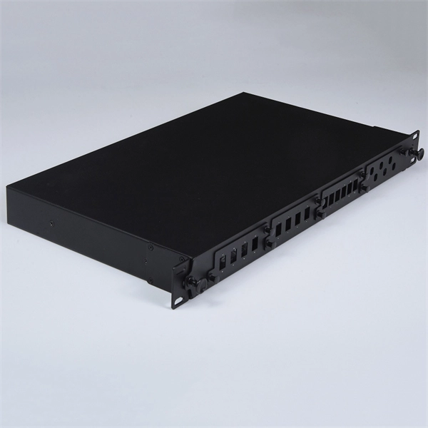
Chad power strips and PDU power distribution units for surface mount, rack mount and general purpose applications. Multiple outlet power strips are manufactured in accordance to Chad standards with agency approvals. Quality Chad power strips, in stock, for standard duty applications up to. Lex Products offers a full range of portable power distribution boxes and units, specifically engineered for indoor and outdoor use for the entertainment, industrial and military industries. Our power distribution boxes range from 20-800 Amps and are well known for being durable, long lasting and. United Rentals is a leading provider of power distribution equipment for rent, featuring cables, transfer switches and power distribution boxes. Whether you're planning an event or managing backup power in case of outages, our team of experts can find the right power distribution rental equipment. PREMIUM CONSTRUCTION POWER DISTRIBUTION BOX: Crafted by WESTERN, the 6506TLSX Temp power box features a durable blend material for long-lasting performance in demanding environments. Our custom-based products are able to match up your distinct needs.
[PDF]
Here we design a LASER diode driver circuit with adjustable voltage regulator LM317 to drive red color 650nm 50mW laser diode. The function of the Laser diode driver is to provide a constant current to t.
[PDF]
In this step-by-step tutorial, we'll cover: ✅ Tools you need ✅ Safety precautions ✅ Mounting the box ✅ Wiring tips ✅ Final checks Perfect for beginners, DIYers, and electricians who want a clear installation guide. more Learn how to properly install an electrical. Learn how to install a distribution box safely and correctly. Covers wiring, placement, standards, and expert tips for a compliant setup. A distribution box is the heart of any electrical system. It takes the incoming power and safely distributes it to different circuits throughout your building. Before starting the installation, finding a proper place for putting the distribution box is crucial, because it largely decides the safety and convenience of maintenance. Let's see what factors need to be taken care of when choosing the installation place. Whether it is residential buildings, commercial facilities or industrial sites, the. Dear Mr. Electrician: How do I install an electrical box in a narrow space? NOTE: Text links below go to applicable products on Amazon. As an Amazon Associate, I earn from qualifying purchases. Using my links helps to keep this website FREE. Warm reminder: Do not disassemble or modify without experience and professionals. Select location Before.
[PDF]

In this tutorial video, we will show you step-by-step how to safely and effectively remove an optocoupler from a circuit board using desoldering wick. We will walk you through the tools you will need, the proper technique for using the desoldering wick, and the precautions to take to av. more In. Whether you're replacing a faulty component, salvaging parts from an old board, or correcting a soldering mistake, knowing how to desolder effectively is essential. This guide will walk you through the tools, techniques, and best practices for desoldering components from a circuit board safely and. Desoldering is a process that removes the solder and components from a printed circuit board or any other type of electronic assembly. This is a meticulous process and it can easily damage the board, or the components, if not properly done. Thus, it is important to know how to desolder properly. If you're desoldering a battery from a circuit board, use flush cutters to cut each wire one-at-a-time to isolate the battery before you desolder the wires. Whenever possible, create an indirect path by soldering connectors onto the battery and the circuit board. This reduces the chance of an. Sorry, an unexpected error has occurred. Why Publish? The Ultimate Guide to Desoldering: From using desoldering irons to sketchily knocking breadboard components off on the side of a table, there are tons of ways to remove components from a circuit board.
[PDF]