Optical pulses traveling through multimode optical fibers encounter the influence of both linear disturbances and nonlinearity, resulting in a complex and chaotic redistribution of power among different modes. I.
[PDF]

The fusion method fuses the fiber cores together with less attenuation. Fusion splicing stands out as a superior technique for joining optical fibers, offering a seamless, low-loss connection that is crucial for reliable fiber optic networks. Thorlabs offers a varied selection of single mode (SM), polarization-maintaining (PM), multimode (MM), and double-clad fiber couplers, as well as 1x8 and 1x16 SM PLC splitters; 1x4, 1x8, and 1x16 PM PLC splitters; wideband multimode circulators; RGB combiners; and WDMs. Our SM and double-clad fiber. Castor's Multimode Fiber Splitters (MFS) are designed to efficiently split or combine multimode signals with minimal insertion loss. Manufactured with step-index fibers with core diameter ranging from 50 to 400 µm, they offer uniform splitting ratios across output channels. This method provides a simple, rugged, and compact method of splitting and combining optical signals. Let's explore the fundamentals of mechanical and fusion. A fiber optical coupler (splitter/combiner) route signals to their appropriate destination by splitting, combining or tapping optical signals/channels in a fiber transmission link. Employing a unique fiber fusing process, Lfiber is now able to fabricate and offer a wide variety of fiber optic. Fused couplers are ideal components to split or combine light signals between two fibers over a wide wavelength and temperature range.
[PDF]
Multimode Fiber Optic Receivers are devices designed to interpret information contained in optical signals transmitted through multimode fibers. These receivers convert the optical signals into electrical signals, allowing the data to be processed and utilized by electronic systems. Multimode Fiber. They convert electrical signals into optical signals for transmission over fiber-optic cables and reverse the process at the receiving end. Now, the term 'multimode' stems from the fact that these transceivers use multimode fiber (MMF) cables, which can carry multiple beams of light — or 'modes' —. Multi-mode optical fiber is a type of optical fiber mostly used for communication over short distances, such as within a building or on a campus. Multi-mode links can be used for data rates up to 800 Gbit/s. Most systems operate by transmitting in one direction on one fiber and in the reverse direction on another fiber for full duplex operation. For applications where long-haul transmission is unnecessary, multimode SFP modules offer a practical. They have a wider core (around 50 to 62. 5 micrometers), which enables multiple modes or light paths to coexist within the fiber, thus resulting in modal dispersion at shorter distances but reducing its efficacy over longer stretches. The choice between Single-Mode Fiber (SMF) and Multimode Fiber.
[PDF]

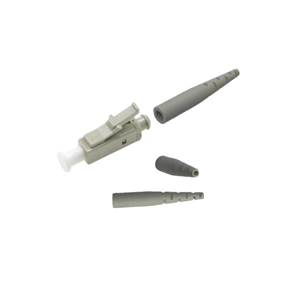
How to Terminate a Multi-mode Fiber Optic Cable with LC mechanical fast connectors. Fusion Splicer: For joining two fibers permanently by fusing them. Safety Equipment: Gloves and safety glasses are crucial to protect against the tiny glass shards of fiber optics. Adhere to industry standards such as. Here are the detailed epoxy LC connector assembly and termination instructions for both single mode and multimode LC connectors. The steps are pretty generic and are applicable to most major brands' LC connectors on the market, such as those from 3M, Seiko, Corning, Molex, AMP, etc. Here are the LC. We terminate fiber optic cable two ways - with connectors that can mate two fibers to create a temporary joint and/or connect the fiber to a piece of network gear or with splices which create a permanent joint between the two fibers. Inject glue Use special glue, insert the glue bottle from the tail handle, squeeze the glue bottle until glue overflows from the end of the ceramic ferrule. Remove the glue bottle and set the connector aside for later use. LC Multimode & Singlemode Connector Termination Instructions Put on safety glasses and prepare work area by organizing all necessary tools from the Fiber Termination Kit (P/N: FTERM-L2), LC Upgrade Kit (P/N: FTERM-LC) and the Consumables Kit (P/N: FT-CKIT-L2). Place primer bottle into primer stand.
[PDF]

Rodent damage in underground or aerial installations. Symptoms: Gradual performance decline over months/years. UV exposure degrading jacket materials. Use Case: Identifying macrobends, breaks, or sharp bends in. In the high-stakes world of optical networking, even a minor disruption in a Pigtail Fiber connection can cascade into costly downtime, affecting data centers, telecom services, or industrial systems. This article equips engineers and network operators with actionable strategies to diagnose. Fiber pigtail failures can lead to unexpected signal loss, link instability, and repeated maintenance. Understanding how to identify early warning signs can help reduce downtime and protect your network from unnecessary failures. A visual check is often the first step when diagnosing a defective. However, when signal loss occurs in a 12 fiber pigtail, it can lead to disruptions in network performance, such as decreased data transfer speeds, increased error rates, or even complete outages. Understanding the potential causes of signal loss and implementing effective troubleshooting methods is. Executive Summary: A fiber optic pigtail is one of the most commonly specified yet least understood components in structured cabling. Dust or oil contamination leads to signal loss. Always clean fibers before splicing. Using the wrong connector (LC vs SC) can cause compatibility.
[PDF]

However, essentially, optical fiber patch cords are more like "finished connection lines", while optical fiber pigtails are "semi-finished connectors". The difference in this core positioning determines the vast disparity between them in structure, connection methods. Executive Summary: A fiber optic pigtail is one of the most commonly specified yet least understood components in structured cabling. Get the wrong connector type, the wrong polish, or skip proper fusion splicing technique—and you're looking at elevated signal loss, increased back reflection, and a. When you build or upgrade a fiber network, the same four words pop up everywhere— fiber optic (bare fiber), pigtail, patch cord, optical cable. They're related, but they are not interchangeable. Mixing them up drives costs higher, increases loss, and slows your rollout. The good news? Once you nail. A fiber pigtail is typically a fiber optic cable with one end factory pre-terminated fiber connector and the other exposed fiber. It is usually suitable for field termination using a mechanical or fusion splicer. The connector end plugs into devices like transceivers or patch panels, while the bare end is typically fusion spliced to a fiber optic cable. This setup ensures. As outlined in T13: Fiber Optic Fundamentals, an optical fiber is a coaxial cylindrical dielectric waveguide with a core refractive index exceeding that of its cladding.
[PDF]
Single mode and multimode fiber optic cables are two different types of fiber optic cable aimed at different use cases. Single mode cables are typically made with a single strand of glass at their core, leading to a n.
[PDF]
To apply fusion hair extensions yourself, section your clean, dry hair, melt a keratin-tipped extension strand with a fusion heat tool, and bond it to a small strand of your natural hair near the root. Repeat section by section, ensuring even spacing and consistent heat. Fusion extensions (also called keratin bond or K-tip extensions) are one of the most natural-looking and long-lasting extension methods available. Each strand is tipped with keratin, which is melted and bonded to your natural hair using a heat tool. While the process offers a long-lasting and natural-looking result. Fusion bond hair extensions, also known as keratin bond extensions or hot fusion extensions, are a semi-permanent hair extension method that uses a keratin bond to attach individual hair extensions to the client's natural hair. The keratin bond is melted using a heat application tool and then. Purchase human or synthetic hair wefts of hair to match your hair. Divide your hair into sections and secure the top in a ponytail. Key features include using small keratin bonds that attach the.
[PDF]
This guide compares multimode cable prices across OM1–OM5 and explains what really moves the number: fiber grade, fiber count, jacket rating, and whether assemblies are factory-terminated. What Factors Affect Fiber Optic Cable Pricing? Several factors influence how much you'll pay for fiber optic cables: Fiber Type and Count: Single-mode fiber typically costs $0. 50 per foot for the cable itself, while multimode fiber ranges from $0. Higher strand counts. Whether you need singlemode, armored, or indoor plenum, this guide gives you the exact cost per foot of fiber optic cable — including installation — so you can budget without guesswork. Data aggregated from Q1 2026 contractor invoices across Texas, Ohio, and North Carolina. This guide outlines typical cost ranges and the main drivers behind pricing to help formulate a budget and estimate expenses. We outline typical ranges for bare cable versus jumpers, note common mistakes when budgeting, and provide a. Fiber optic cables are essential components in today's broadband, FTTx, and data center networks. Whether you're planning a national fiber rollout or sourcing cables for enterprise infrastructure, understanding how fiber optic cable pricing works can help you budget more effectively and make better.
[PDF]
A fiber-optic switch allows you to connect two or more fiber-optic cables to form a network. These can behave like a typical Ethernet switch. With a fiber switch combined with a fiber network adapter, you could connect fiber directly to your desktop computer or. Multimode fiber (MMF) is an optical fiber designed to carry multiple light propagation paths—or modes—simultaneously. This is made possible by its relatively large core diameter, typically 50 or 62. 5 microns, compared to the ~9-micron core in single-mode fiber. The wider core accepts light from. Multi-mode optical fiber is a type of optical fiber mostly used for communication over short distances, such as within a building or on a campus. Multi-mode links can be used for data rates up to 800 Gbit/s. Assuming Auto-MDIX is not enabled on these devices, drag the appropriate type of cabling on the left to each connection type on the right. In this blog post, we will discuss the key features and. This article describes the common types of fiber optic cable used for data transmission. Ubiquiti also provides branded optic SFP/SFP+ modules (tranceivers) that are fully compatible with all of our devices. See the page for more information. Back to Top Fiber optic cabling is an alternative to.
[PDF]
A8: Yes, multimode fiber optic cable can support high-speed data transmission depending on the fiber type and network equipment used. Multimode fiber (MMF) is an optical fiber designed to carry multiple light propagation paths—or modes—simultaneously. This is made possible by its relatively large core diameter, typically 50 or 62. 5 microns, compared to the ~9-micron core in single-mode fiber. The wider core accepts light from. Multi-mode optical fiber is a type of optical fiber mostly used for communication over short distances, such as within a building or on a campus. Multi-mode links can be used for data rates up to 800 Gbit/s. Multi-mode fiber has a fairly large core diameter that enables multiple light modes to be. In the realm of telecommunications and networking, multimode fiber optic cable plays a crucial role in efficiently transmitting data over short to medium distances. This guide aims to provide a concise understanding of multimode fiber optic cable and its applications. These fiber cables are structurally designed to transmit several light signals simultaneously, each of which is directed. Unlike copper cables, which rely on electrical signals, fiber optics use pulses of light to transmit data—offering unmatched bandwidth, low interference, and long-distance capabilities. But not all fiber cables are created equal: multimode (MM) and single mode (SM) fibers are the two primary types.
[PDF]

This guide aims to provide a concise understanding of multimode fiber optic cable and its applications. We will explore its characteristics, advantages, specifications, and real-world uses. Multimode fiber (MMF) is an optical fiber designed to carry multiple light propagation paths—or modes—simultaneously. This is made possible by its relatively large core diameter, typically 50 or 62. 5 microns, compared to the ~9-micron core in single-mode fiber. The wider core accepts light from. Multimode fiber optic cables are essential in modern data communication systems since they can transmit data efficiently and at high speeds over short and medium distances. We will explore its. They consist of a transmitter on one end of a fiber and a receiver on the other end. Most systems operate by transmitting in one direction on one fiber and in the reverse direction on another fiber for full duplex operation. Most systems use a "transceiver" which includes both transmission and. Multi-mode optical fiber is a type of optical fiber mostly used for communication over short distances, such as within a building or on a campus. Multi-mode links can be used for data rates up to 800 Gbit/s.
[PDF]
VIAVI offers the industry's most complete range of optical attenuators for installation and maintenance of singlemode and multimode fibers and advanced, photonic-layer solutions for lab and production environments. Fibertronics, Inc. provides an extensive selection of fiber optic attenuators tailored to meet diverse needs. These attenuators are suitable for use in single mode 9/125, multimode 50/125, and multimode 62. Our male-to-female buildout optical attenuation (Pads) are available. Attenuators from VIAVI offer a complete range of power-balancing options, from fixed to variable optical attenuators in field, lab, and manufacturing environments. These operate by collecting and collimating light from an input fiber and then reflecting this light off of an ultra-stable and reliable, single-axis DiCon MEMS mirror. 1 The animation shows how to adjust and lock the attenuation. Thorlabs' Multimode Variable Fiber Optic Attenuators (VOAs) allow one to attenuate an optical signal easily by plugging multimode fibers or components directly into the attenuator. Our VOAs leverage advanced technologies including fiber-to-fiber direct coupling—free of lenses and coatings—for ultra-broad. Fiber optic attenuators are devices used to reduce or monitor the power level of a fiber optic signal. Basic types of fixed attenuation include single mode, dual window and multimode in D4/PC, FC, FC/UPC, MU, SC, SC/APC and UPC, ST and ST/UPC style connectors. Optical attenuators usually work by.
[PDF]
Join Jake from Omnitron in this comprehensive tutorial. Understand the nuances of single-mode and multimode fibers, and how to bridge the gap using media converters. Enhance your tech knowledge and. But what happens when you need to connect an existing multi-mode campus network to a new single-mode service provider link? You can't just splice them together. This is where fiber conversion comes in. This guide will break down the professional methods to achieve seamless single-mode to multi-mode. Single-mode (SMF) and multi-mode fiber (MMF) use different core sizes, sources and wavelengths. These differences determine which transceivers work with which fiber and how far signals can travel. Let's analyze the differences between multimode and single-mode fiber to understand why networks require fiber mode conversion and. How can we convert the multimode to a singlemode fiber system? This complete guide will provide answers to these questions. That is because SMF and MMF have. There are two main types of fiber optic cables: single mode and multimode. Although they can do the same job in some instances, the different construction methods make each of them better suited to certain tasks and budgets. What if end B is located in another building, dozens of kilometers far away from end A? Or end B equipment is single-mode or must use a single-mode fiber connection? In the former case, you.
[PDF]