The soft starter wiring diagram typically includes information about the power supply, motor connections, control circuit, and bypass arrangement. It helps in understanding the complete wiring arrangement and makes it easier to troubleshoot any potential issues. See Technical Data TD03900001E. We are guided by our commitment to do business right, world's most urgent power management challenges. A proper wiring diagram is crucial to ensure the soft starter functions effectively and protects the motor from any kind of damage. Whether you're a professional electrician or a DIY enthusiast, this detailed wiring diagram and installation guide will help you understand the c. more. Soft starters are widely used to reduce the current surge when devices are started and to provide ramped acceleration to motors. The use of soft starters can reduce energy costs by up to 15%, as well as providing protection from damage caused by voltage sags or electrical faults. Connecting the soft starter to a wye motor inserts the SCRs directly in the line wiring, referred to as "In Line" wiring. If the motor is hard. If you're looking to install a soft start system in your electrical setup, it's crucial to understand the wiring diagram that goes along with it. A soft start system is designed to gradually increase the voltage and torque to a motor, reducing the initial inrush current and protecting both the.
[PDF]

Wiring Direction: Wiring between the main circuit breaker and each branch circuit breaker in the box generally goes on the left, and the wiring out of the distribution box generally goes on the right. Binding Requirements: The wires should be bound with. Learn how to wire a distribution box step by step! This video shows real on-site footage of electrical installation, demonstrating safe and standardized wiring methods used by professionals. Whether you're a professional or a DIY enthusiast, understanding the correct procedure can prevent accidents and ensure optimal performance. This guide provides step-by-step. Hey, in this article we are going to see the Single Phase Distribution Box Wiring Diagram and Connection Procedure. A distribution board or distribution box is where the main power supply is distributed to multiple loads. Students utilize various electrical components, including circuit breakers and cables, and are guided to apply. Correct wiring methods for circuit breakers within distribution boxes are fundamental to ensuring electrical safety and compliance with established codes. The distinction between 1P and 2P circuit breakers plays a pivotal role in determining the appropriate protection level for various circuits. Connection method: Each switch takes a wire from the incoming point and connects it to the incoming end of the switch, or uses parallel connection to reduce the difficulty of wiring.
[PDF]
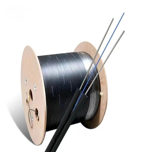
Professional quotes from experienced fiber optic cable installation contractors are crucial for accurate project estimates, as the costs of fiber optic cabling can vary significantly based on location, terrain,.
[PDF]
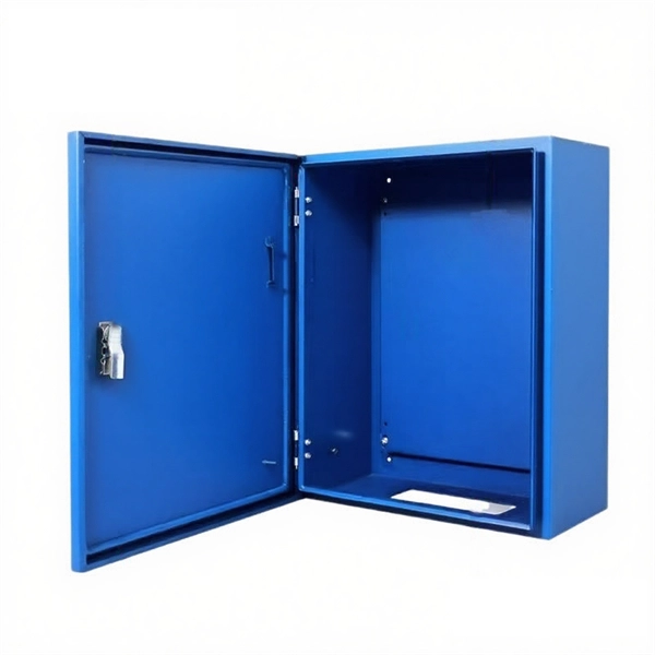
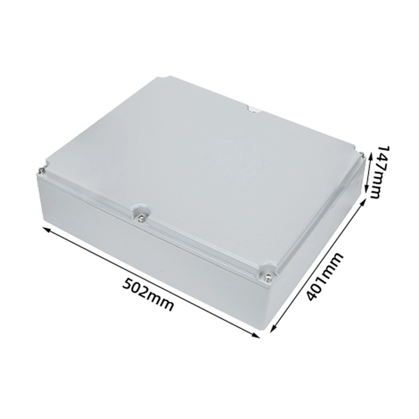
A neat, well-organized subpanel bundles wires to conserve space and improve access. Ideally, wire groups are installed in layers and wires are bent at right angles to buses or breakers. Label short sheathing sections (slugs) to indicate which circuits wires serve. Choose the right box based on environment (indoor/outdoor), load capacity, and durability. Check for proper IP/NEMA ratings and material quality. Ensure safe placement: install in. Welcome to this live training session! ⚡ In today's tutorial, I'll be demonstrating how to arrange cables neatly inside a distribution bo. more See what others said about this video while it was live. Wire color: The neutral wire is blue, and the color of the phase wire (A phase is yellow, B phase is green, and C phase is red). It consists of various protective and control devices for electricity distribution in a building. 📌At the top, there are main circuit breakers and residual current devices (#RCDs), which protect against overcurrent and leakage currents. 📌The middle section includes an electric energy meter that. Wiring distribution panels serve as the central hub and nerve center, routing power from the main service feed to multiple circuits. When setting up such a significant component of industrial, commercial, and utility applications, it's essential to get everything right. When wiring distribution.
[PDF]
Download new and previously released drivers including support software, bios, utilities, firmware and patches for Intel products. trol I/O is desired. The Q-SYS Core 24f satisfies a broad spectrum of application needs from meeting room environments, conferencing systems, retail establishments, houses of worship, judicial environments, education institutions and other general purpose pro essing applications. A Core 24f may be. That change is why correct leads and connections matter for system stability and lifespan. Please sign in or register for an Intel account. Automatically update your drivers and software Use this tool to identify your products and get driver and. Purpose: This connector serves as the main junction, transmitting essential electrical currents from the supply unit to the motherboard. Design: It features a distinct arrangement of multiple connectors, each designated for specific functions, ensuring balanced and stable power distribution. Product replacement Get replacements and find substitutions for discontinued Schneider Electric products. Where to buy Search our network of verified distributors with over 15,000 sales outlets. Communications bus and supply power terminal blocks, functions, ratings, requirements, and cables provides information about the functions, ratings, and requirements for the communication bus and supply power terminals; and guidelines for wire sizes, cable types, and cable lengths when wiring the.
[PDF]
Check the electrical load and ensure that the sensors do not exceed the 10 Amp maximum. Check each wire for damage that may lead to a short. Replace any damaged cables. Check the tightness of electrical connections along the. In modern power systems, distribution boxes are the core equipment for power distribution and control, and their stable operation is crucial to ensuring the safety and reliability of power supply. However, in actual applications, distribution boxes often encounter a series of problems, which not. The Electrical Distribution Box is a very important part of the power system, improper installation will cause a lot of danger and loss. Here are some things that go wrong with an Electrical Distribution Box installation: Poor contact of the ground wire: The ground wire is the safety guarantee of. When it comes to electrical work, the small details inside a junction box can make a big difference in safety and performance. Even experienced DIYers sometimes make simple wiring mistakes that can lead to tripped breakers, poor connections, or potential fire hazards. It ensures smooth power flow, efficiently distributing electricity to various systems. However, like any other electrical device, a 3 Phase Electrical Distribution. They tell you if electricity is flowing through the wire. With your tester, check the flow of electricity at each wire before it enters the box. Using a light switch as a simple example, check each of the three wires.
[PDF]
Ensure safe placement: install in dry, accessible areas with good ventilation and at appropriate height (typically ~1. Practice good wiring: secure grounding, neat cable management, proper insulation, and correct wire gauge and breaker size. Learn how to wire a distribution box step by step! This video shows real on-site footage of electrical installation, demonstrating safe and standardized wiring methods used by professionals. As a key control device connecting the upper and lower levels of the power system. This booklet is issued primarily as a convenient reference for customers, architects, engineers, and contractors planning or constructing buildings or installing, repairing, or renewing apparatus or equipment to be connected to the Company's distribution system. Any reference herein to the Company. Connection method: Each switch takes a wire from the incoming point and connects it to the incoming end of the switch, or uses parallel connection to reduce the difficulty of wiring. Wiring Direction: Wiring between the main circuit breaker and each branch circuit breaker in the box generally. Distribution board is a safe system designed for house or building that included protective devices, isolator switches, circuit breaker and fuses to safely connect the cables and wires to the sub circuits and final sub circuits including their associated Live (Phase) Neutral and Earth conductors. Include protection devices like breakers, fuses, and.
[PDF]
Basic: 100A indoor replacement — Panel, new breakers, basic wiring; 6–8 hours; total $1,200–$2,000; includes standard permit where required. Key cost drivers include panel amperage, indoor vs outdoor location, wiring length, and whether a full panel upgrade or rerouting is needed. The article outlines cost ranges, per-unit pricing, and practical. Typical cost ranges for replacing a distribution box or service panel in the United States vary widely based on panel size, amperage, labor, and whether a full service upgrade is needed. A low-amp subpanel costs from $500 to $1,000 while a 200-amp panel upgrade runs up to $4,000. Total costs depend on the type of home, the number of circuits, and the amperage. Our homes are. Upgrading or installing a residential electrical panel in the San Francisco Bay Area is a significant project that must meet California's stringent safety codes. This article outlines the cost factors, price ranges, and practical budgeting advice for a U. The price depends on electrical code upgrades, permit. Electrical service line replacement costs $225 to $500 for your project, based on your home's setup and access. Your home's layout and local code set your total wire length, especially from the meter to breaker box. Your project needs permits and utility coordination, and underground service lines.
[PDF]

This guide shows you how to organize circuit breaker wiring properly. You will learn to build a safe, efficient, and professional electrical system today. Circuit breaker wiring configurations involve organizing main switches, busbars, and branch breakers within a distribution box. Messy distribution boxes are dangerous and very hard to fix. It takes the incoming power and safely distributes it to different circuits throughout your building. Whether in a home or an industrial facility, this box keeps your electrical setup organized, functional, and efficient. The distinction between 1P and 2P circuit breakers plays a pivotal role in determining the appropriate protection level for various circuits. Learn how to wire a distribution box step by step! This video shows real on-site footage of electrical installation, demonstrating safe and standardized wiring methods used by professionals. It serves as a central hub for distributing electricity throughout a building, ensuring that power is delivered safely and efficiently to all the required locations. At the heart of a breaker box is the main breaker, which controls the flow of electricity from the utility into the building. From the main breaker, power is sent to individual circuit breakers, each of.
[PDF]
This installation note provides the installation instructions for the Cisco small form-factor pluggable (SFP) and SFP+ transceiver modules. This document is intended to serve as a guide for architecting and deploying fiber optic networks in a customer environment. These transceiver modules are hot-swappable input/output (I/O) devices that plug into 100BASE, 1000BASE and 10GBASE ports (for SFP+), which connect the module. This manual provides safety and installation instructions for the 9490-OS Fiber Optic Passive Splitters. All units use type LC connectors and vary only in the splitting fan-out, and as single or dual-channel capability as listed below. Optical fibers require special care during installation to ensure reliable operation. Installation guidelines regarding minimum bend. Listings and approvals under Time Recorder Co. are the property of Tyco Fire Protection Products. Description Multiple Signal Fiber Optic Modems combine multiple system communications signals and convert them to fiber optic communications for transmission. This guide will focus on the 1x9 dual SC optical transceiver products. Pin Assignment & Description TD+, TD: DC coupled LVPECL inputs for the transmitter.
[PDF]
Check for proper IP/NEMA ratings and material quality. Ensure safe placement: install in dry, accessible areas with good ventilation and at appropriate height (typically ~1. Practice good wiring: secure grounding, neat cable management, proper insulation, and correct wire gauge. In this video, we'll walk you through the process of wiring a home distribution box with a detailed connection diagram. Whether you're an electrician or a DIY enthusiast, this guide will help you understand the basics of home electrical distribution. more Welcome to our channel! In this video. However, the key to a safe and reliable system lies in proper installation. If it's done poorly, you risk short circuits, fire hazards, or system failure. Done right, it ensures safety, compliance, and long-lasting performance. In this guide, we'll break down everything you need to know to install. Distribution board is a safe system designed for house or building that included protective devices, isolator switches, circuit breaker and fuses to safely connect the cables and wires to the sub circuits and final sub circuits including their associated Live (Phase) Neutral and Earth conductors. Learn how to wire a single-phase household distribution box in just 60 seconds! In this quick tutorial, we'll cover the essential components and wiring steps for a safe and efficient distribution setup in residential areas.
[PDF]

In the following tutorial, we will show how to wire 120V single-phase and 240V split-phase circuit breakers and loads inside a residential main panel. The figure below shows a typical breaker panel used for 120V and 240V circuits. Messy distribution boxes are dangerous and very hard to fix. You will learn to build a safe, efficient, and professional electrical system today. Circuit breaker wiring configurations involve organizing main switches, busbars. A breaker box, also known as a circuit breaker panel, is an essential component of any electrical system. It is responsible for distributing electricity throughout a building, ensuring that each circuit receives the proper amount of power. To understand how a breaker box works, it is helpful to. Each circuit is protected by a circuit breaker, a safety device that automatically shuts off power if it detects an overload or a fault. If you're looking to replace an old fuse box replacement or upgrade your home's power capacity, you'll be dealing with the load center or service panel. The distinction between 1P and 2P circuit breakers plays a pivotal role in determining the appropriate protection level for various circuits. When installing or troubleshooting a power distribution system, understanding how to correctly connect the main electrical supply to the control panel is crucial.
[PDF]

Ensure safe placement: install in dry, accessible areas with good ventilation and at appropriate height (typically ~1. Practice good wiring: secure grounding, neat cable management, proper insulation, and correct wire gauge and breaker size. The term “four wires” refers to three live wires and one neutral wire, designated as A|B|C|N|, with N representing the ground wire. The three live wires should be connected to the upper entry of the main switch in the explosion-proof distribution box, and the neutral wire should be directly. Learn how to wire a distribution box step by step! This video shows real on-site footage of electrical installation, demonstrating safe and standardized wiring methods used by professionals. This ensures compliance with NEC and simplifies troubleshooting. Include protection devices like breakers, fuses, and. Prevention of Electrical Hazards: Proper wiring ensures that electrical currents flow smoothly and safely through the circuits, minimizing the risk of electrocution and electrical accidents. Faulty wiring can result in electric shocks and even be life-threatening. Efficient Power Distribution: The. ormal operation due to poor manufacture quality. A paid repair will be provided if the warranty period expires. For any damage due to one of the following situations, a paid repair duct, please dispose the pro ype, a “R” is added after the Specification. For single row 20, and circuit 24, fter.
[PDF]
An Ethernet splitter consists of two RJ45 jacks, one on each side. These jacks are used to connect the Ethernet cable to the splitter. Depending on the type of splitter you have, there may also be other ports or connectors that need to be connected as well. A wiring diagram for an Ethernet splitter can make the installation process a breeze. It does not increase speed or create extra bandwidth. It simply divides signal pairs. This tool works best in basic setups where running another cable is not possible. An Ethernet splitter. An Ethernet Splitter works by separating a single line into two or more outgoing lines, allowing multiple users to draw from the same source without affecting bandwidth. You may also want to know: Are Bing and Yahoo the Same? · Are Sony and Murata Partners? The term “Ethernet splitter” is often. Repeat step 2 to connect a second Network Device to the Cable Adapter. To view manuals, FAQs, videos, drivers, downloads, technical drawings, and more, visit www. to an existing Network. Scenario: A company has two offices (A and B). A single CAT5 Ethernet drop.
[PDF]
The 11-in-1 Screwdriver includes the 8 bits and 3 nut drivers most requested by professionals. The bit prevents bit wear from hardened screws and extends bit life when fastening specialty screws found in elec.
[PDF]