Download new and previously released drivers including support software, bios, utilities, firmware and patches for Intel products. trol I/O is desired. The Q-SYS Core 24f satisfies a broad spectrum of application needs from meeting room environments, conferencing systems, retail establishments, houses of worship, judicial environments, education institutions and other general purpose pro essing applications. A Core 24f may be. That change is why correct leads and connections matter for system stability and lifespan. Please sign in or register for an Intel account. Automatically update your drivers and software Use this tool to identify your products and get driver and. Purpose: This connector serves as the main junction, transmitting essential electrical currents from the supply unit to the motherboard. Design: It features a distinct arrangement of multiple connectors, each designated for specific functions, ensuring balanced and stable power distribution. Product replacement Get replacements and find substitutions for discontinued Schneider Electric products. Where to buy Search our network of verified distributors with over 15,000 sales outlets. Communications bus and supply power terminal blocks, functions, ratings, requirements, and cables provides information about the functions, ratings, and requirements for the communication bus and supply power terminals; and guidelines for wire sizes, cable types, and cable lengths when wiring the.
[PDF]

A beamsplitter is a common optical component that partially transmits and partially reflects an incident light beam, usually in unequal proportions. In addition to the task of dividing light, beamsplitters can be employed to recombine two separate light beams or images into a single. Beamsplitters are fundamental components in optical engineering, serving to precisely divide a single input beam of light into two distinct output beams. This division allows for the simultaneous analysis or utilization of the light's properties along two separate paths. It is a crucial part of many optical experimental and measurement systems, such as interferometers, also finding widespread application in fibre optic telecommunications. a laser beam) into two (or sometimes more) beams, which may or may not have the same optical power (radiant flux). Different types of beam splitters exist, as described in the. The beam splitter splits and then recombines infrared radiation, while the detector picks up the resulting signal. It's sensitive to both intensity and frequency. Together, they decide just how accurately an instrument captures those unique infrared “fingerprints” from different substances.
[PDF]
In this guide, we'll break down everything you need to know to install a distribution box correctly and confidently. Choose the right box based on environment (indoor/outdoor), load capacity, and durability. Check for proper IP/NEMA ratings and material quality. A distribution box is the heart of any electrical system. It takes the incoming power and safely distributes it to different circuits throughout your building. Whether in a home or an industrial facility, this box keeps your electrical setup organized, functional, and efficient. However, the key to. In modern electrical systems, cable distribution boxes (also known as electrical distribution boxes or distribution boxes) play a crucial role as the key hub for managing, distributing, and protecting circuits. Just like travelers need clear pathways and safety protocols, your electrical circuits need proper management to prevent chaos. This article details the process of installing them, which helps you comprehend distribution boxes. Learn how to wire a distribution box step by step! This video shows real on-site footage of electrical installation, demonstrating safe and standardized wiring methods used by professionals. Site selection requirements: The distribution box should be installed in an area close to the power supply to reduce.
[PDF]

Towers are not rooted by only pouring concrete—they require extensive soil analysis, wind loads, types of towers, and seismic activity to determine the necessary foundation for safety and sustainable use. A communication tower foundation design is the structural blueprint that determines the anchor point of the tower on the ground. This article delves into the intricate process of civil construction tailored. Tower owners must comply with a multi-layered regulatory, engineering, and safety framework that governs tower siting, where a cell tower can be built, how it must be designed, and how it operates throughout its lifecycle. These requirements ensure public safety, structural integrity, regulatory. Here are six foundation types for communication towers that work for a wide range of situations and environments. If you're planning a new installation, knowing the basics of these foundations can help you establish a secure and durable tower that will be a community asset for years to come. Telecom (Telecommunications) towers are a generic description of radio masts and towers built primarily to hold telecommunications antennas. As such antennas often have a large area and must be precisely pointed out, such towers have to be designed and built to limit wind induced movement. The Contractor shall employ a quality control program that will ensure that engineering, fabrication.
[PDF]
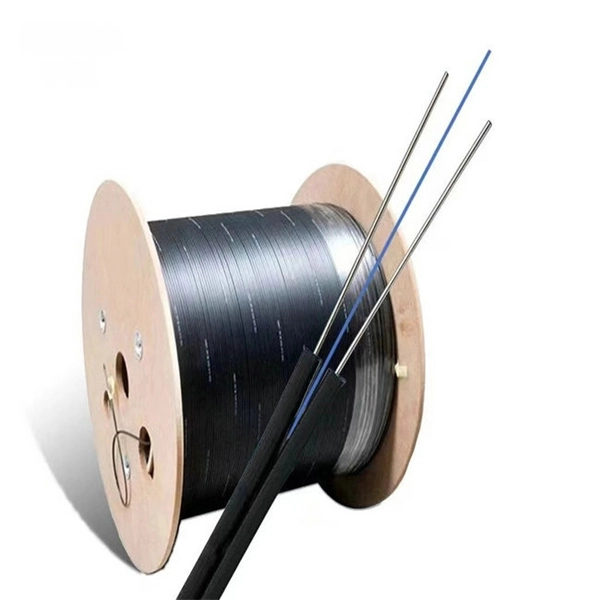
Recommendation ITU-T L. 163 describes criteria for the installation of optical fibre cables defined in Recommendation ITU-T L. 110 in remote areas with lack of usual infrastructure for installation including the procedures of cable-route planning, cable selection, cable-installation. The Fiber Optic Association, Inc. (FOA) was founded in 1995 to help develop the workforce to build the fiber optic networks to support a rapid expansion in communications and the Internet. The charter of the FOA was to promote professionalism in fiber optics through education, certification, and. specifications under which the various work for trenching & laying of optical fiber cable are to be executed by the Vendor. The broad guidelines as laid down by TEC India, for laying of OFC networks are to be followed. Underground cables are pulled in conduit that is buried underground, usually 1-1. 2 meters (3-4 feet) deep to reduce the likelihood of accidentally being dug up. In extreme cold climates, cables may need to be buried at greater depths where there. If we can reduce failures and increase the service life of optical cables by carrying out communication optical cable construction in a standardized manner, it is worth understanding and learning for us telecommunications construction workers. To this end, overhead optical cable construction.
[PDF]

Support Portal provides access to various services for Nokia Customers and Partners, such as Product Documentation, SW Downloads, Ticket Creation and Case Handling. The latest generation of Digital Coherent Optics (DCO) pluggable transceivers represents a breakthrough in the optical networking industry. By combining advances in silicon photonics and Digital Signal Processors (DSP) with Quad Small Form-factor Pluggable – Double Density (QSFP-DD) form factor. Ciena's WaveLogic 6 Extreme 1. 6T quantum-safe encryption solution on the Waveserver platform was designed with this in mind, supporting QKD system interworking and NIST-certified PQC algorithms. It delivers an always-on, wire-speed encryption solution, without impacting performance or adding. 400 Gigabit Ethernet (400G) transceivers are optical modules capable of handling data rates of 400 Gbps. With a transmission rate of up to 400 Gbps, 400G transceivers offer double the capacity of their predecessor (200G transceivers). 400G. ONU, or Optical Network Unit, is a networking device that connects your home or business to the internet using fiber optic cables. It's like a bridge between the vast internet world and your personal network. ONU is a small device that sits somewhere in your house. When you connect your computer. C-Data's ONU products include models that offer data, data + voice, data + CATV, and Triple Play services. They support TR-069 and provide excellent compatibility with third-party OLT systems.
[PDF]