
Towers are not rooted by only pouring concrete—they require extensive soil analysis, wind loads, types of towers, and seismic activity to determine the necessary foundation for safety and sustainable use. A communication tower foundation design is the structural blueprint that determines the anchor point of the tower on the ground. This article delves into the intricate process of civil construction tailored. Tower owners must comply with a multi-layered regulatory, engineering, and safety framework that governs tower siting, where a cell tower can be built, how it must be designed, and how it operates throughout its lifecycle. These requirements ensure public safety, structural integrity, regulatory. Here are six foundation types for communication towers that work for a wide range of situations and environments. If you're planning a new installation, knowing the basics of these foundations can help you establish a secure and durable tower that will be a community asset for years to come. Telecom (Telecommunications) towers are a generic description of radio masts and towers built primarily to hold telecommunications antennas. As such antennas often have a large area and must be precisely pointed out, such towers have to be designed and built to limit wind induced movement. The Contractor shall employ a quality control program that will ensure that engineering, fabrication.
[PDF]

This section explains that Article 250 focuses on general grounding and bonding electrical installation requirements, including: The grounding of systems, circuits, and equipment. Which circuit conductor must be grounded. Learn about the general requirements for grounding and bonding in line with the NEC 2023. The purpose of grounding is the safety of people and property. Grounding and bonding limit overvoltages, stabilize the voltage to the ground during regular functioning, and ease the proper operation of circuit. Electrical grounding is the process of connecting the non-current carrying parts of your home's electrical system—like metal boxes and appliance chassis—to the earth. In the event of a fault, such as a live wire touching a. Correct grounding of services depends upon understanding the definition and role of the grounded conductor. The neutral conductor is typically the grounded conductor connected to the system's neutral point, carrying current under normal operation. Grounding electrode conductors must be connected at. Properly grounding an electrical panel is one of the most critical safety measures in any home's electrical system. It is a non-negotiable requirement for protecting against severe electrical shocks, preventing electrical fires, and safeguarding sensitive electronics from power surges. The main goal of grounding is to limit voltages caused by lightning, line surges, or accidental contact with.
[PDF]

Choose the right box based on environment (indoor/outdoor), load capacity, and durability. Check for proper IP/NEMA ratings and material quality. Ensure safe placement: install in dry, accessible areas with good ventilation and at appropriate height (typically ~1. The National Electrical Code (NEC) provides comprehensive safety standards for electrical installations, including requirements for electrical panels (main service panels and subpanels or breaker box). NEC Article 408 covers switchboards, switchgear, and Panelboards installation and applications. In this guide, we'll break down everything you need to know to install a distribution box correctly and confidently. Just like travelers need clear pathways and safety protocols, your electrical circuits need proper management to prevent chaos. 26 requires electrical equipment (including electrical panels) to be located to provide required working clearances about the equipment. You can find electric panels inside cabinets, behind refrigerators, or inside clothes closets in older homes. Current National Electrical Codes (NEC) allow none of these locations. Expect to pay $1,500 to $2,000 to move an electrical panel, with replacement adding another $1,150 if your existing box needs upgrading.
[PDF]

The National Electrical Code (NEC) has established eight levels of fire resistance for fiber optic cables. These levels are based on the time it takes for a cable to burn through or melt. Corning Optical Communications manufactures quality flame retardant optical fiber cables for indoor applications, which comply with the requirements of the National Electric Code® (NEC® 2023) published by the National Fire Protection Agency (NFPA). To ensure compliance to these requirements, a. Understanding the listing requirements of fire alarm circuit cables can help you make sense of the cable alphabet soup. Here are some highlights from Part IV of Article 770. There's plenty of "expansion room" built into Article 770. Part I ends with Section 770. 44. Cabling Installation & Maintenance - Classes 1, 2, 3, and 4, communications, fire alarm, and optical fiber cables are all addressed in the NEC. By Stanley Kaufman, PhD, CableSafe Inc. UL Solutions' long-standing history in certification and Standards development makes us a trusted thought leader in the. Understanding the fire ratings and jacket options for fiber optic cables is crucial for ensuring optimal performance and safety. This technical guide will provide a comprehensive overview of these factors, their implications on cable resilience and transmission, and tips for making informed.
[PDF]
Distance relays, also known as impedance relay, differ in principle from other forms of protection in that their performance is not governed by the magnitude of the current or voltage in the protected circuit but rather on the ratio of these two quantities.OverviewIn, a protective relay is a device designed to trip a when a is detected. The first protective relays were electromagnetic devices, relying on coils operating on moving par. Electromechanical protective relays operate by either, or. Unlike switching type electromechanical with fixed and usually ill-defined operating voltage thresholds.
[PDF]
MTF-01 is an optical flow ranging integrated sensor developed by MicoAir Technology. It uses uart to output data and is compatible with mainstream open source flight controllers such as Ardupilot, PX4 and INAV. It can be used directly after simple configuration without complicated. The micolink is a lightweight protocol customized by MicoAir Tech, prepared for developers who are ready to write their own code to read sensor data. MicoAssitant software can used for configure protocol or other parameter of MTF-01. Step1 : Connect the MTF-01 to PC by using the USB to TTL module. The is a lightweight 2 in 1 optical flow sensor including a short range lidar which uses the serial MAVLink protocol to communicate with the autopilot. This can be used to improve horizontal position control especially in GPS denied or indoor environments. Users can switch communication protocols through the USB to UART TTL module, adapting to different flight control systems. Easy to Operate:. MTF-01 and MTF-01P use more powerful TOF sensors, providing a longer range. The MTF-01P also utilizes a laser light source, extending the maximum range to 12 meters, and includes an injection-molded casing. Featuring the MTF-01 module, it delivers precise optical flow data, enhancing drone stability and maneuverability. With the PMW3901 sensor, it provides accurate 8-meter laser ranging.
[PDF]

Optical fiber technology has revolutionized the way we communicate, enabling fast and reliable data transmission over long distances. In this article, we will explore the different types of optical fibers used in communication systems and their applications. Fiber Optics or Optical Fiber is a technology that transmits data as a light pulse along a glass or plastic fiber. An Optical Fiber is a cylindrical fiber of glass that is hair-thin in size or any transparent dielectric medium. The fiber which is used for optical communication is waveguides made of. Optical fibers are the backbone of modern communication. They transmit light signals over long distances with minimal loss. Let's break down their classification in a simple and engaging way: 1. The less signal damage metal wires can cause, the better for optical fiber connection. Total internal reflection (critical angle, using Snell's law). Higher bandwidth (extremely high data transfer rate). Less signal degradation. Less costly per meter. Lighter and thinner then copper wire. The light is a form of carrier wave that is modulated to carry information. The cladding's refractive index is slightly smaller than that of the core, which confines light within the core and propagates by repeated total reflection at the boundary with the.
[PDF]
An optical transport network (OTN) is a digital wrapper that encapsulates frames of data, to allow multiple data sources to be sent on the same channel. This creates an optical virtual private network for each client signal. ITU-T defines an optical transport network as a set of optical network elements (ONE) connected by optical fiber links, able to provide functionality of transport, multiplexing, swit. EquipmentAt a very high level, the typical signals processed by OTN equipment at the Optical Channel layer are: • SONET/SDH• Ethernet/FibreChannel• Packets. • - Details of all OTN areas including breakdown of the full frame Anritsu Poster - Details of all OTN areas including breakdown of the full frame at the Wayback Machine (archived 2014-05-17)•.
[PDF]

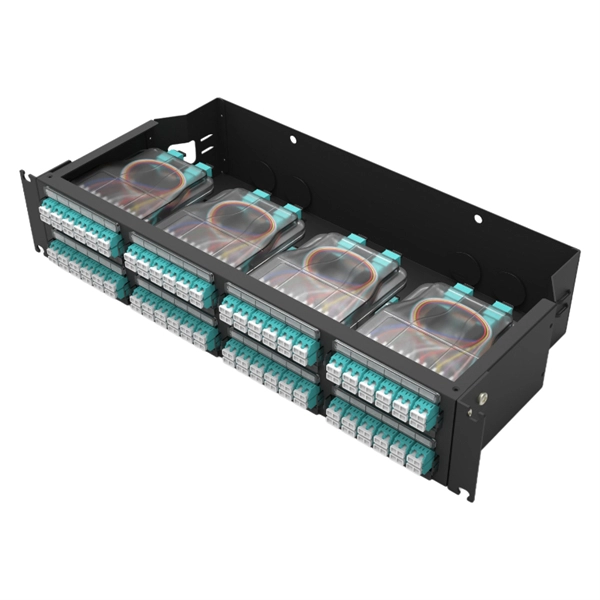
While traditional fiber optic cables contain individual fibers encased in a protective jacket, ribbon fiber cables organize fiber optic strands in a flat ribbon structure, creating freedom with space conservation and cable management. Data Centers: The flexible ribbon cables deliver phenomenal bandwidth between densely packed servers and networking gear in data centers. Motor Meter: Ribbon cables can be used to connect the control circuitry to the display or to the motor drivers. Telecom Devices: In telecommunications, flat. Ribbon cables offer higher fiber counts and greater fiber density than any other cable construction designed for the outside plant (OSP), four times the highest-fiber-count loose tube cable. Ribbon cables also enable mass-fusion splicing, whereby each 12-fiber ribbon can be spliced in a single. The technology of ribbon fiber optic cables is well-established in the telecommunications industry and is favored for its high fiber density and compact size. Join us as we embark on a journey of discovery, demystifying the technology that has changed the way we connect and communicate. Welcome to the world of Ribbon Fiber Optic Cables. One of our most innovative technologies is the ribbon fiber optic cable —a compact, powerful solution that is transforming the way organizations manage high-density connections while optimizing valuable space. In this article, we'll delve into why ribbon fiber optic cables are a game-changer, how.
[PDF]

Explore our comprehensive SFP optical module selection guide for 2025. Learn about crucial factors like data rate, distance, fiber type, and compatibility to optimize your network performance and cost-effectiveness. Make informed decisions for your networking needs today!. SFP (Small Form-factor Pluggable) is a compact, hot-pluggable network interface module used to connect network devices (switches, routers, firewalls) to fiber optic or copper cables. They're essential for extending network distances and increasing bandwidth capabilities. Selecting the correct SFP module is not simply a matter of matching connectors. In modern Ethernet networks, choosing the wrong transceiver can result in link failures, speed mismatches, compatibility errors, or unexpected distance limitations. For network engineers, system integrators, and IT. At the core of these advanced networks are bidirectional SFP modules, also known as BiDi SFP transceivers—compact, cost-efficient devices that support high-speed data transmission and reception over a single optical fiber. By using different interfaces and single-mode or multimode fiber depending on the.
[PDF]

Optical amplifiers work differently. They amplify the light directly, with no conversions. This process is faster, more efficient, and keeps the signal clearer. Using optical amplifiers helps reduce signal distortion, lowers system costs, and supports long-distance communication. The most common types include: Erbium Doped Fiber Amplifiers (EDFA): EDFAs are the most commonly used type of optical amplifier in telecommunications. They play a vital role in modern optical communication systems, enabling the transmission of high-speed data over long-haul networks. An optical amplifier is a device that boosts the strength of an optical signal. 2dB per kilometer for 1. This means that over a distance of 100km, a signal can lose around 20dB. This principle dictates that a photon can interact with an atom already in an excited energy state, forcing the excited atom to immediately release its stored energy as a second photon. It does this without changing the light into an electrical signal. In the past, systems used repeaters to fix weak signals. These repeaters turned light into electricity, boosted the signal, and then. The SPIE Digital Library offers a comprehensive range of content on optical amplifiers, reflecting their significance in modern photonics and telecommunications. The library includes a variety of peer-reviewed papers, conference proceedings, and technical articles that delve into the fundamental.
[PDF]
Recommendation ITU-T L. 163 describes criteria for the installation of optical fibre cables defined in Recommendation ITU-T L. 110 in remote areas with lack of usual infrastructure for installation including the procedures of cable-route planning, cable selection, cable-installation. The Fiber Optic Association, Inc. (FOA) was founded in 1995 to help develop the workforce to build the fiber optic networks to support a rapid expansion in communications and the Internet. The charter of the FOA was to promote professionalism in fiber optics through education, certification, and. specifications under which the various work for trenching & laying of optical fiber cable are to be executed by the Vendor. The broad guidelines as laid down by TEC India, for laying of OFC networks are to be followed. Underground cables are pulled in conduit that is buried underground, usually 1-1. 2 meters (3-4 feet) deep to reduce the likelihood of accidentally being dug up. In extreme cold climates, cables may need to be buried at greater depths where there. If we can reduce failures and increase the service life of optical cables by carrying out communication optical cable construction in a standardized manner, it is worth understanding and learning for us telecommunications construction workers. To this end, overhead optical cable construction.
[PDF]

For renewable energy applications, specifically in wind and solar power plants, the IEEE C37. 232 standard specifies the requirements for relay protection of these systems. For those not familiar with the different elements that form a WEP, commonly known as a Wind Farm, this report introduces a description of the different elements comprising a wind farm and how their unique characteristics may be considered to provide a proper design. For successful application of. Abstract—A wind electric plant (WEP) is made of many wind turbine generators spread over a large area and includes many subsystems that need to be protected. It is important to ensure that all the subsystems are well protected and coordinated to maximize the reliability (security and dependability). Protection of Wind Electric Plants is a report covering engineering considerations for the design of protection systems and present relay protection and coordination practices at wind electric plants. The report includes protection of generator step up transformers, collector system feeders. In this paper, the performance of classical protection functions of two commercial relays (denoted as A and B) are investigated. The relays are tested in a Hardware-In-the-Loop environment and the strengths and weaknesses of these functions are determined. These specialized switches serve as crucial safety mechanisms that isolate circuits.
[PDF]

