
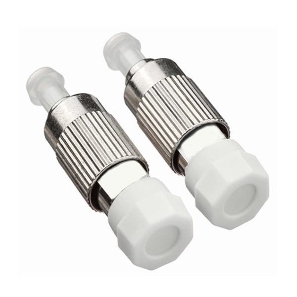
5 dB depending on splitter type. Common planning value: 0. Optional: patch panels, attenuators, or extra components. Helps cover dirt, aging, and measurement tolerances. Adds Rx power and margin calculation. Calculate insertion loss for passive optical splitters in PON and distribution networks. Power is divided equally among output ports. Excess loss accounts for manufacturing imperfections, typically 0. DISCLAIMER: These calculators are provided for. Optical splitters, encompassing FBT (Fused Biconical Taper) couplers and PLC (Planar Lightwave Circuit) splitters, are prevalent passive optical devices designed to divide fiber optic light into multiple segments based on a specified ratio. Fiber optic splitters are vital components within. In fiber optic networks, particularly in FTTx (Fiber to the x) and PON (Passive Optical Networks) deployments, splitters play a central role in distributing the optical signal from a single source to multiple destinations. Optional: patch. Understanding optical splitter loss isn't just about plugging numbers into a calculator. It's about knowing what factors contribute to that loss, how manufacturers specify it, and how it impacts the overall performance and reach of your network. Understanding the types of splitters, their impact on network performance, and how to measure their losses ensures high-quality network operation and facilitates optimal splitter selection based on.
[PDF]
We calculate cable tray weight using the formula: Volume × Material Density. The calculation accounts for side rails, rungs, and cross-bars. Find the volume of the cable tray: This depends on the dimensions (width, height, thickness) and length of the tray. Multiply the volume by the material density: This gives you the total weight. Now, let's look at the specifics of Cable Tray Weight Calculation for each tray type. Channel trays are. The calculation of cable tray weight relies on the following formula: Weight (kg) = Material Density (kg/m³) × Total Volume (m³) To apply this formula, you need: Material type profoundly influences tray weight and suitability. 00 for bare tray weight. Used only when cover is selected. Used to estimate joints/couplers. Set to zero if unknown. Typical 200–300 mm spacing. rung bar. Height of the Cable Tray You Have: mm Weight Capacity of the Cable Tray You Have: kg/m RESULTS Total dia of all cables: 0. 00kg/m Width of all cables: 0. 00mm YOUR SELECTION ANALYSIS WIDTH CHECK: HEIGHT CHECK: WEIGHT CHECK: REMAINING CABLE. Values are applicable to all resin systems, where possible.
[PDF]
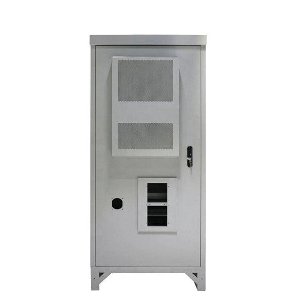
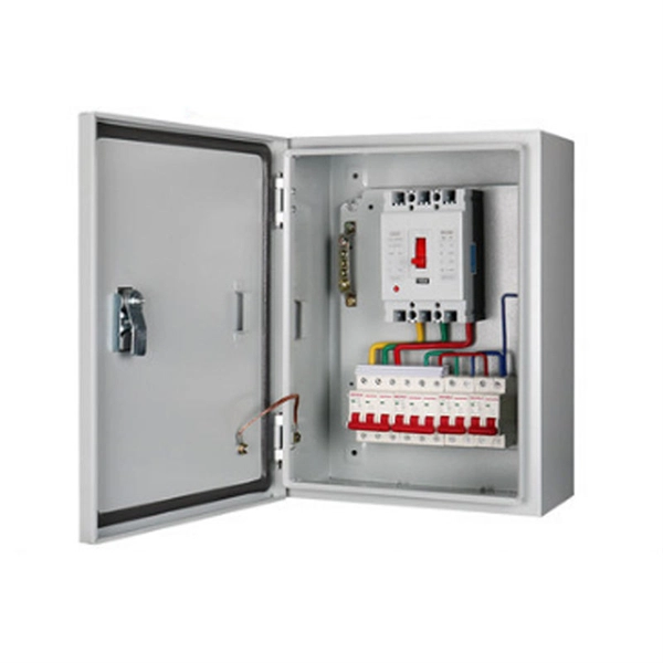
Proper installation of an electric meter box is essential for safety, code compliance, and smooth coordination with your utility provider. A small mistake in mounting location or wiring can lead to failed inspections, service delays, or fire risks. A meter box is an electrical enclosure designed to house the electricity meter and related service connections. It acts as the formal interface between the utility power supply and the consumer's internal electrical system. That small enclosure becomes a shared responsibility. Electricians install it. Utilities connect it. If the location is wrong, the issue spreads quickly:. Panelboards shall be installed in accordance with the listing of the panelboard. The National Electrical Code (NEC) provides comprehensive safety standards for electrical installations, including requirements for electrical panels (main service panels and subpanels or breaker box). NEC Article 408. Limited the meter location from pad mount transformer for PSO. Removed unistrut being listed as an alternative means for mounting the meter box. APCo and TX do not allow unistrut for installations. 7/2020 Revised Figure 15. Added wording for consistency with Section 8 of document. The utility company uses this reading for billing. Its primary purpose is to safely contain the meter, protect internal.
[PDF]

In this video, we'll walk you through the process of resurrecting y. The test sets display a laser warning icon when the laser source is active to alert the user about a potentially dangerous situation. It is recommended to: Deactivate the laser before connecting or disconnecting optical cables or patchcords. more Is your optical power meter showing no signs of life? Don't worry; we've got you covered! In. Introduction The RP460 Optical Power Meter is an ultra low cost, and compact power meter used for verifying both absolute and relative power across any given fiber. This document will serve as an overview of the major features and functions of the device and will offer tips for trouble shooting. Fiber Optical Powermeter User Manual | FS Title Author Subject Keywords Created Date. The OPM1315 is a newly developed portable optical power meter. It is equipped with a 1. 0 mm large area detector so that stability and reliability can be enhanced effectively. This unit is designed to fit the hand comfortably, and can be used for installation, debugging, and maintenance of any fiber. ments to the instrument's performance and functionality. The figures given in this manual ion of this manual to ensure the accuracy of its contents. However, should you have any questions or fi gistered users with a variety of information and services. Please allow us to serve you best by.
[PDF]
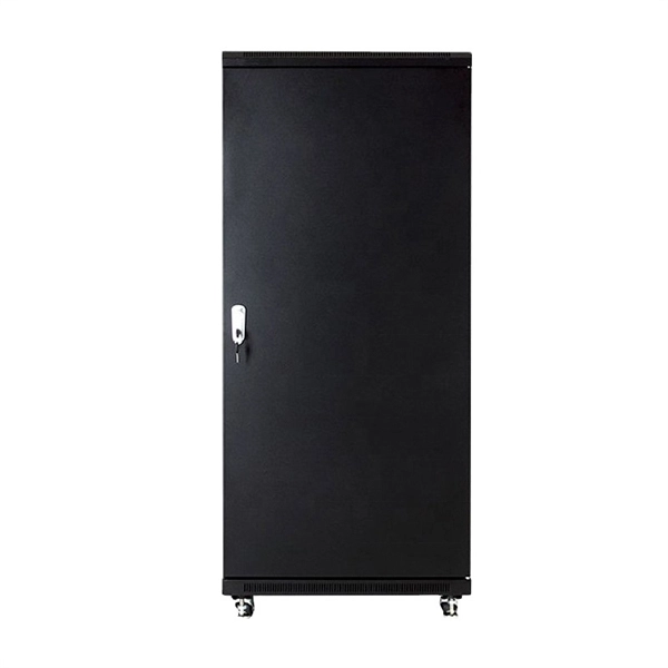
Unlock the top 14 rack PDUs with intelligent metering to enhance your data center's power management—discover the essential features and options to consider. Raritan is a proven innovator of power management solutions, DCIM software and KVM-over-IP for data centres of all sizes. Working across 76 countries and 50,000 locations worldwide, Raritan boasts award-winning hardware and software solutions that stand to increase energy efficiency and. More detailed competitive analysis can be found in our Data Center Rack Power Distribution Unit (PDU) Report. Get analysis tailored to your specific needs and decision criteria. I've found several top smart PDUs with monitoring features perfect for power management in 2026, including models like the Intellinet 8-Port PDU. The top 10 PDU companies leading the market in 2025 are APC by Schneider Electric, Eaton Corporation, Vertiv, CyberPower Systems, Legrand, Tripp Lite, Server Technology, Raritan, Panduit, and Geist. These industry leaders excel through strong market share, innovative product offerings, and. Leading global PDU manufacturers offer innovative solutions tailored to meet diverse needs, from basic power distribution to advanced intelligent systems. By selecting a trusted provider, you can enhance energy efficiency, reduce downtime, and optimize your operations. Understanding the top players.
[PDF]

The OPM 510 and 520 are available in standard and high-power versions for the Telco and MSO markets. The OPM510 and OPM520 supports wavelengths of 850, 980, 1270 1300, 1310, 1490, 1550, 1577, 1623 and 1650nm. The rugged enclosure provides confidence when testing singlemode and. Count on Tempo Communications Optical Power Meters (OPM510/520) to test and maintain your fiber optic networks. Our optical power meters feature built-in calibration factors. Optical power meters and detectors have been served by Newport for over 30 years. The offering ranges from a low cost, hand-held meter to the most advanced dual channel benchtop power meter available in the market. Our 1936-R/2936-R series boasts state-of-the-art analog boards with a whopping 250. © Copyright© Santec Holdings Corporation. Demo the full range, from multi-use to dedicated PON and FTTH. VIAVI offers fast, cost-effective, and easy-to-use power meters for installation and maintenance of single mode and multimode fiber optic networks and. AFL is a trusted supplier of optical testing equipment with more than 30 years of experience and tens of thousands of units in use in the field. AFL's full range of power meters are used for testing single-mode and/or multimode fiber networks. Power meters with wave ID can detect two or more.
[PDF]
GELU Systems introduces a new line of intelligent PDUs with switched and metered outlets. Tri-color lighted outlets bring a new level of visual status with 360 degree viewing angle. From basic reliable power distribution to advanced remote monitoring and switching capabilities, find the perfect match for your infrastructure. Network-grade power distribution with individual outlet control, metering, and environmental monitoring. Designed for high-density compute environments. iPDUs serve as a centralized power management solution that enhances the efficiency, reliability, and monitoring capabilities of power. Leaders in rack power distribution units for nearly 40 years, Server Technology PDUs are the choice for Fortune 100 companies to technological startups. Removable display module with front or side mount capability allows easy access to LCD screen and control dial even. PWG2 Intelligent PDU offers advanced power management with real-time monitoring and control. Its features include remote access, customizable alerts, and easy integration, ensuring efficient energy use and reduced operational costs. Ideal for enhancing data center performance and scalability. Powertek is a leading global manufacturer of high-quality, customized rack power distribution units (PDUs), basic and intelligent PDUs, inline meters, automatic transfer switches (ATS), power splitters and environmental sensors for datacenters and IT-professionals. Because power is all we do since.
[PDF]
We calculate cable tray weight using the formula: Volume × Material Density. The calculation accounts for side rails, rungs, and cross-bars. Find the volume of the cable tray: This depends on the dimensions (width, height, thickness) and length of the tray. Multiply the volume by the material density: This gives you the total weight. Now, let's look at the specifics of Cable Tray Weight Calculation for each tray type. 00 for bare tray weight. Used only when cover is selected. Used to estimate joints/couplers. Set to zero if unknown. Typical 200–300 mm spacing. rung bar. The calculation of cable tray weight relies on the following formula: Weight (kg) = Material Density (kg/m³) × Total Volume (m³) To apply this formula, you need: Material type profoundly influences tray weight and suitability. Below is a reference for common materials and their densities, crucial. Height of the Cable Tray You Have: mm Weight Capacity of the Cable Tray You Have: kg/m RESULTS Total dia of all cables: 0. 00kg/m Width of all cables: 0. 00mm YOUR SELECTION ANALYSIS WIDTH CHECK: HEIGHT CHECK: WEIGHT CHECK: REMAINING CABLE. When installing a cable tray, it is vital to make sure that the correct weight capacity of the tray is determined. Calculating the weight of a cable tray is not always.
[PDF]

Select the correct wavelength and set your reference. You measure optical power in dBm or insertion loss in dB. Consistent procedures ensure accuracy. Measure total signal loss from fiber, connectors, or splices. Optical fiber attenuation is the attenuation per unit length of optical fiber, and the unit is dB/km. When connecting two optical fibers, there will be loss inside any connector or joint. Consistent measurement techniques. While optical power meters are the primary power measurement instrument, optical loss test sets (OLTSs) and optical time domain reflectometers (OTDRs) also measure power in testing loss. TIA standard test FOTP-95 covers the measurement of optical power. Optical power is based on the heating power. Light Source: The CMA5 Series Light Sources provide an economical and stable laser source for use in point-to-point attenuation measurement. They feature a rugged design, built to withstand the difficult testing environment of fiber optic cable installation and maintenance. The CMA5 Light Sources. When talking about optical measurements, wavelength basically means how far a wave pattern repeats itself, usually measured in nanometers (nm). Commonly, a power meter on its own is used to measure absolute.
[PDF]
ONU, o Unidad de Red Óptica, se refiere al dispositivo terminal óptico dentro de una red de acceso de fibra. Proporciona a los usuarios múltiples interfaces de servicio, convirtiendo señales ópticas en señale.
[PDF]
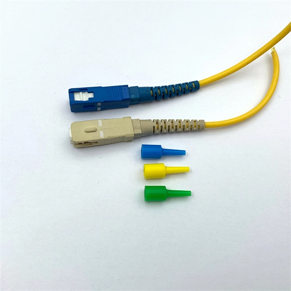
Learn how to identify and prevent these common issues. Installing a fiber optic patch panel may seem straightforward, but many network issues originate from small installation mistakes. Poor fiber routing, incorrect bend radius, or improper labeling can all lead to signal loss, maintenance difficulties, and unexpected downtime. This article highlights. What Can Go Wrong with Copper Patch Panels? What Can Go Wrong with Copper Patch Panels? Are you aware of the problems that a copper patch panel can cause in your network infrastructure? Learn how to identify and prevent these common issues. However, installation errors can lead to issues that impact network performance. This article offers guidance on proper installation and troubleshooting. Network patch panel, cable manager, network cable, wire stripper, crimping tool, zip ties. Use a small yellow tool or wire stripper to remove the outer jacket of the network cable. Cut off the cross-shaped skeleton of the Cat6 patch cord. Insert. Our guide delivers actionable, step-by-step best practices for rack layout, cable management, and patch panel installation. Many seasoned pros (and plenty of first-timers) run into avoidable pitfalls that turn a simple installation into a costly headache.
[PDF]
A passive optical network (PON) is a fiber-optic telecommunications network that uses only unpowered devices to carry signals, as opposed to electronic equipment. In practice, PONs are typically used for the last mile between Internet service providers (ISP) and their customers. In this use, a PON has a point-to-multipoint topology in which an ISP uses a single device to serve many end-us. Components and characteristicsA passive optical network consists of an (OLT) at the service provider's central office (hub), passive (non-power-consuming) optical splitters, and a number of (ONUs) or. Passive optical networks were first proposed by in 1987. Two major standard groups, the (IEEE) and the. A PON takes advantage of (WDM), using one wavelength for downstream traffic and another for upstream traffic on a (ITU-T, typically OS2). BPON, EP.
[PDF]

This manual describes Inspect, a command-line tool for debugging TNS C/C++, COBOL, FORTRAN, Pascal, Screen COBOL, and TAL programs and snapshots on HP NonStopTM TNS/R and TNS/E systems. MFT (Mellanox/NVIDIA Firmware Tools) is a set of firmware management utilities for querying firmware details, performing firmware upgrades, and other configuration tasks. It includes four main components: mst, mlxburn, flint, and Debug Utilities. For full specifications, refer to the official. All commands were tested on HP/Aruba 5400 switches (specifically 5406Rzl2), but will work on any model with recent firmware versions (16. x or newer), except for the hardware features unavailable on smaller models, like VSF. This publication supports J06. 03 and all subsequent J-series RVUs, H06. Show general info: current CPU load, uptime, memory used/free, software. The HP 1-Port 1GbE Flex IO NIC is designed to work in the Flex IO port of select HP systems. Refer to platform specifications for compatibility. It utilizes a Realtek RTL8153 10/100/1000 Ethernet controller to provide an additional 1GbE LAN Port. 3az-2010, also known as Energy. HPE Insight Diagnostics is a hardware diagnostic tool. To start iLO with keyboard and monitor connected to the box - press F8 while booting Invoke virtual serial port. Starting text console. Press 'ESC (' to return to the CLI Session.
[PDF]

The complete process for terminating cable runs at a patch panel, from mounting and cable management to punch-down, labeling, and testing every port. To wire a patch panel: Mount the panel in your rack. If you're still deciding which panel style fits your site (keystone vs punch‑down vs pass‑through), start with How to choose a patch panel and come back here once the hardware is locked in. 60-second answer If you want reliable results, the winning recipe is simple: keep pair twists tight right up. Network patch panel, cable manager, network cable, wire stripper, crimping tool, zip ties. Use a small yellow tool or wire stripper to remove the outer jacket of the network cable. Cut off the cross-shaped skeleton of the Cat6 patch cord. Insert. Patch panels make cable management and network organization very easy over long periods of time, but you'll need to wire the panels in order to put them into your network. Not to worry, this guide will walk you through the whole process. Before you jump into the task, ensure that you have the. Testing a patch panel is an essential task to ensure the reliability and efficiency of a network infrastructure. The process verifies the end-to-end connection, ensuring the cable is properly terminated at the wall jack and at the distribution point, such as a switch or patch panel.
[PDF]
PAM4 is a modulation scheme that combines two bits into a single symbol with four amplitude levels as shown in Fig. This effectively doubles a network's data rate, enabling 400G/800G short-haul transmission. NRZ, or Non-Return-to-Zero signaling, represents binary information using two distinct signal levels: This creates relatively wide signal separation between logical states. As a result, NRZ systems historically provided: This operational tolerance helped earlier architectures remain relatively. PAM4 is a branch of the pulse amplitude modulation (PAM) technology, which is a mainstream signal transmission technology following non-return-to-zero (NRZ). Playing a key role in multi-order modulation, PAM is widely used in high-speed signal interconnection. Figure 1-1 shows the typical waveform. A key new modulation scheme, PAM4, was introduced around 2017 and enabled the big jump from 100G to 400G. When it comes to enabling 400G and higher Ethernet speeds, a four-level pulse amplitude modulation or PAM4 multilevel signaling is needed as opposed to the non-return-to-zero (NRZ) modulation.
[PDF]

