A solar meter, also known as a solar irradiance meter or pyranometer, is a device that measures the amount of solar energy or irradiance emitted by the sun. It is commonly used in solar power applications to op.
[PDF]

This guide will walk you through the process of checking photo sensors using a multimeter, covering various types of photo sensors, the necessary tools and safety precautions, and the specific measurement techniques involved. Knowing how to effectively use a multimeter to test photo sensors can save you time, money, and frustration when dealing with malfunctioning devices. more What is a Voltage Divider? | What is a Voltage. Before replacing the sensor or fixture, it's efficient testing it first, With a few tools and a step-by-step process you can find whether your outdoor lighting control system is working as intended or if the problem lies elsewhere. In this complete guide from Lead-Top, a global leader in photocell. In this blog post, we explain step-by-step how to troubleshoot a sensor with a digital multimeter (DMM). Here are the steps: Troubleshooting a sensor measurement failure requires mechanical tools to uncover the protective shields or components so you can reach the sensor in question. Always follow the manufacturer's instructions for the sensor and multimeter. Ensure the sensor is properly connected to the multimeter and. A multimeter is an indispensable diagnostic tool for anyone working with electronics, electrical systems, or indeed, sensors. It's a versatile device capable of measuring voltage, current, and resistance, providing crucial insights into the health and functionality of electrical circuits and.
[PDF]

The fastest way to test a fluorescent tube is with a multimeter set to continuity mode. Each end of the tube has two pins connected by a thin filament inside the glass. If either filament is broken, the tube is dead. The whole test takes about 30 seconds per tube once you know what. This is a complete guide for testing a fluorescent light bulb with a multimeter. You don't have to be an expert in electrical work. This process measures electrical resistance to determine if the tube has suffered an internal failure before replacing the bulb or investigating the ballast. This guide provides a comprehensive understanding of the process, equipping you with the knowledge and. To test a fluorescent light bulb, observe any of the following: flickering light, low brightness, buzzing sound, delayed start, and fading color and light variation. Turn off the power to the circuit that powers the fixture and keep the leads steady to ensure accurate readings. Multimeters provide. How to Test Light Bulbs & Fluorescent Tubes with a Multimeter (Continuity Check) Is your lamp or fixture failing to light up? Before you buy a new bulb, you need to confirm if the bulb or tube itself is the problem! A simple continuity check using a multimeter can instantly tell you if the filament.
[PDF]
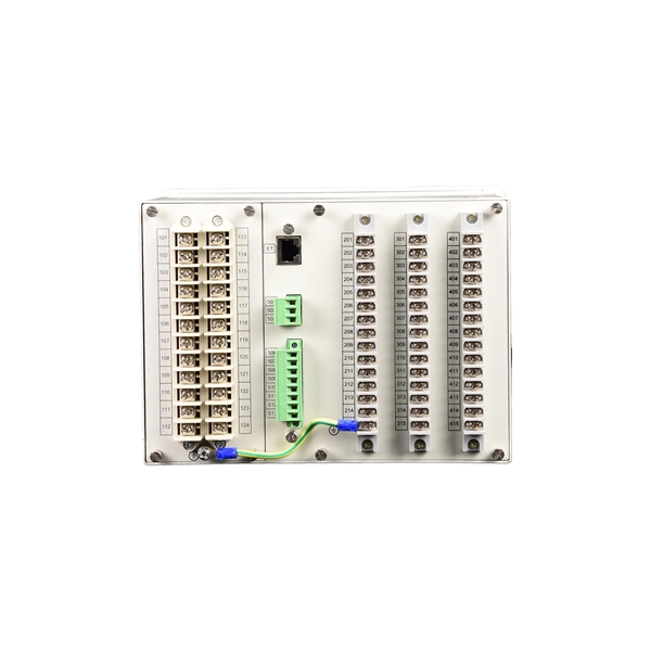
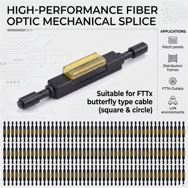
In an Ethernet patch panel diagram, each port on the patch panel is represented by a numbered or labeled square or circle. The diagram typically includes details such as the port numbers, cable types, and the devices connected to each port. Ethernet patch panel diagram is a visual representation of the connections between Ethernet cables and network devices, such as switches and routers. It provides a clear overview of how the network is structured, allowing network administrators to easily troubleshoot and manage the network. This information can be used to track the location of devices, their serial numbers, and their IP addresses. Change Management: Patch panel connection diagrams can be used to track. A patch panel is an essential component in a network system that provides a central location for connecting multiple devices or cables. The patch panel serves as. A pair of managed Gigabit Ethernet rack-mount switches, connected to the Ethernet ports on a few Panduit patch panels using Category 6 patch cables. (All equipment is installed in a standard 19-inch rack. Each port has a patch connection that links it to another port in another part of your building.
[PDF]

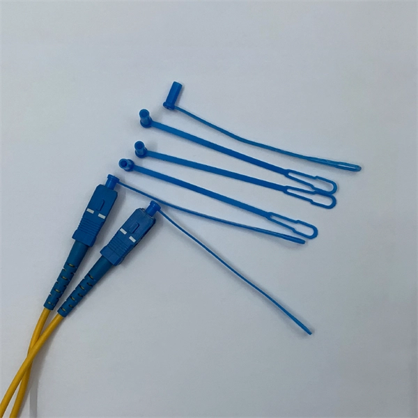
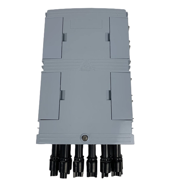
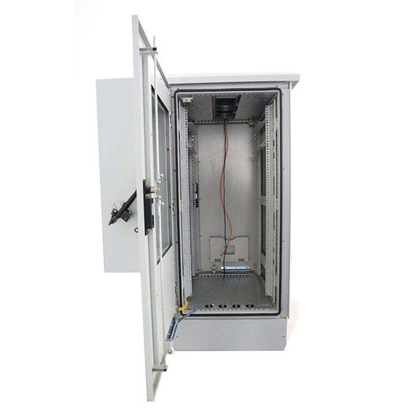
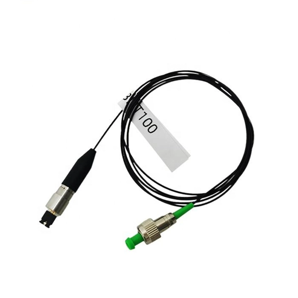
Buy low price 4 Cores Ftth Mini Fiber Optic Terminal Box/patch Panel Gz-idp-a4 by Shanghai Huijue Network Communication Equipment Co., a leading supplier from China. 2848 similar products are also available from global exporters. Capacity: 576 Cores Max. Huijue FTTH Fiber Optic PLC Splitter SC UPC/APC Connector 1x2 1x4 1x8 1x16 White Black Grey 1 Pcs /box 8. Get exactly what you're looking for. Optical fiber active connectors: Optical patch cords, optical fiber connectors, optical fiber patch cords, Optical splitter: Optical fiber coupler, optical splitter, fused coupler, fused taper, planar waveguide optical splitter, plc splitter, coupler, blade type, box type, rack type, lgx, Fiber. 1. IP66 EMC protection 2. United State military standard 3. ISO 9001:2000 OUTDOOR CABINET Summary:J-NET-XF6 series outdoor telecommunication cabinet is maily used in the field of traffic, CATV, electric power etc., Ltd (HJ Network for short) is the leading manufacturer and solution provider for telecom and communication products. The headquarter of HJ Network including the R&D center, technical center, prototype dept and sales is.
[PDF]
A solar meter, also known as a solar irradiance meter or pyranometer, is a device that measures the amount of solar energy or irradiance emitted by the sun. It is commonly used in solar power applications to op.
[PDF]
Our calibration laboratory offers efficient turnaround times and is ISO 17025 accredited. In addition to our calibration and repair services, we can also provide replacement monitors during the repair period and/or offer competitive rates for monitor rental. The Scientific Metrology Department of the Authority's Metrology Division is responsible for the Metrology Laboratories. Three of its laboratories (Temperature, Mass and Pressure) are accredited to ISO/IEC 17025:2005 by DKD. With calibration of measurement instrumentation services from SGS, you can be sure of the highest degree of measurement accuracy, reducing measurement uncertainties. From production facilities, both on and offshore, through to. Amart Ventures Ltd is a pioneering company specializing in calibration services, ensuring the precision and accuracy of a wide range of industrial equipment. With a steadfast commitment to excellence, we cater to diverse industries with a comprehensive suite of calibration solutions. We partner with our customers to provide customer requirements. With a focus on quality control, MetricScale specialize in the calibration and testing of a wide range of equipment and. Metrology is the science of measurement, embracing both experimental and theoretical determinations at any level of uncertainty in any field of science and technology A sound measurement system is an essential element in achieving an effective safety policy. Essential factors for such a system are:.
[PDF]
UTM enables an organization to consolidate their IT security strategy and services into one device, potentially simplifying network protection. As a result, your business can monitor all threats and securit.
[PDF]
Learn how to identify and prevent these common issues. Installing a fiber optic patch panel may seem straightforward, but many network issues originate from small installation mistakes. Poor fiber routing, incorrect bend radius, or improper labeling can all lead to signal loss, maintenance difficulties, and unexpected downtime. This article highlights. What Can Go Wrong with Copper Patch Panels? What Can Go Wrong with Copper Patch Panels? Are you aware of the problems that a copper patch panel can cause in your network infrastructure? Learn how to identify and prevent these common issues. However, installation errors can lead to issues that impact network performance. This article offers guidance on proper installation and troubleshooting. Network patch panel, cable manager, network cable, wire stripper, crimping tool, zip ties. Use a small yellow tool or wire stripper to remove the outer jacket of the network cable. Cut off the cross-shaped skeleton of the Cat6 patch cord. Insert. Our guide delivers actionable, step-by-step best practices for rack layout, cable management, and patch panel installation. Many seasoned pros (and plenty of first-timers) run into avoidable pitfalls that turn a simple installation into a costly headache.
[PDF]
Please view our full RLH price list and contact us at info@fiberopticlink. com if you have any questions or special project needs. A 24-port patch panel is a fundamental component in modern network infrastructure, widely used by IT professionals and network installation service providers. These panels serve as centralized connection points that organize and manage Ethernet or fiber optic cabling within data centers, server. Check each product page for other buying options. Need help? Get reliable 24-port patch panels for voice, data, and video connections. Discover UL-listed options suitable for commercial and professional environments. Among the most widely used configurations is the 24 port fiber patch panel, offering an optimal balance between density and manageability. Love how customizable it is with the ability to add keystone jacks of different types. Free Shipping for many. SNTC-24X7X4 15454 - 2RU 64Ports LC Patch Panel. SP ONSITE 24X7X4.
[PDF]

Regularly testing fiber optic cables helps minimize network downtime, lengthens the network's longevity, reduces maintenance requirements, and helps support network reconfiguration and upgrades. Fiber optic testing ensures the performance and reliability of fiber optic networks. Key tests include: Effective fiber testing utilizes advanced tools such as Optical. Fiber optic testing for continuity is crucial in ensuring that light transmits through fiber optic cables without interruptions, safeguarding seamless data transmission. This guide talks about the primary methods and tools for effective continuity testing in fiber optic cable networks. Insertion loss testing confirms whether the cable meets design loss budgets. OTDR testing identifies events along the fiber length, including: OTDR is essential for long-distance FTTH feeder and distribution cables. After the cables are installed and terminated, it's time for testing. For every fiber optic cable plant, you will need to test for continuity, end-to-end loss and then troubleshoot the problems. If it's a long outside plant cable with intermediate splices, you will probably want to verify the. We'll explain why it's vital to test fiber optic cables, the three most popular methods, and when you should use them. Why Testing Fiber Optic Cables Matters? Regular testing of fiber optic cables is not just a preventive measure; it's an.
[PDF]

The PV combiner box test in solar power systems is a fundamental procedure that verifies the accuracy of string connections and the electrical current flowing to inverters. This test helps prevent energy losses while optimizing system performance. ance cables by combining strings at the array locat ciency, reliability and safety in solar energy systems. They enable centralized management in large-scale and remote installation ity), equipment aging, and poor installation practices. MapperX performs this critical test professionally. This guide provides a step-by-step method for safely testing energized PV strings to locate intermittent ground faults using reliable tools and procedures. What Is an Intermittent Ground Fault? An intermittent ground fault is a temporary electrical connection between a current-carrying conductor. A PV combiner box, often referred to as a solar combiner box, is a critical component in solar energy systems. This device plays a significant role in both residential and commercial solar installations, particularly when. We do a lot of solar PV and renewable energy asset inspections here at HelioVolta and SolarGrade! Every time we visit a site, we use the SolarGrade platform to guide our workflow and document our findings. Missing/Improper Label Improper labeling can be a risk to personnel and should conform to.
[PDF]

This report lists the top Passive Optical Network (PON) Equipment companies based on the 2023 & 2024 market share reports. Mordor Intelligence expert advisors conducted extensive research and identified these brands to be the leaders in the Passive Optical . Global Outlook – By Component (Optical Power Splitters, Optical Filters, Wavelength Division Multiplexer/De-Multiplexe), By Structure (Ethernet Passive Optical Networks (EPON), Optical Network Terminal (ONT), Optical Line Terminal (OLT), Gigabit Passive Optical Network (GPON), Optical Network. As per MRFR analysis, the Passive Optical LAN Market Size was estimated at 25555. 89 USD Million in 2024. The Passive Optical LAN industry is projected to grow from 28704. 79 USD Million by 2035, exhibiting a compound annual growth rate (CAGR) of 12. Need. Discover the innovators and market leaders driving Passive Optical Network technology into a new era. Get expert insights into competitive positioning, market trends, and strategic imperatives for stakeholders. For a deep-dive analysis with in-depth forecasts, download the Passive Optical Network. The global passive optical network (PON) market size was valued at USD 17. 80% during the forecast period. 9% from 2024 to 2030. With the proliferation of bandwidth-intensive applications, such as streaming services, online gaming, and.
[PDF]
The Fiber Patch Panel, also known as a fiber distribution panel or fiber termination panel, serves as a central point for managing and organizing fiber optic cables within a network. What is a Fiber Patch Panel? Fiber optic patch panels are enclosures that act as a distribution hub for fiber cable. A bulk (multi-strand) fiber cable enters the patch panel and then each fiber strand is separated into individual strands or pairs of strands. These individual strands will then. A fiber patch panel is a mounted enclosure—either rack-mounted or wall-mounted—used to terminate, manage, and interconnect multiple fiber optic cables. It acts as a hub for organizing splices and patch cords, streamlining fiber management and preserving signal integrity. Cable Organization:. However, behind an organized fiber-optic network lies an unthinkable hardware device called a fiber patch panel. It helps you keep fiber optic cables neat in your network. You use this device to connect and separate fiber cables. It does not need power to work. Serving as the network's centralized junction, it provides secure ports for both incoming and outgoing. Learn what a fiber optic patch panel is, how it works, and why it is essential in modern fiber networks. A practical guide for FTTH, data centers, and telecom systems. In modern fiber optic networks, reliability, scalability, and ease of maintenance are just as important as transmission speed.
[PDF]
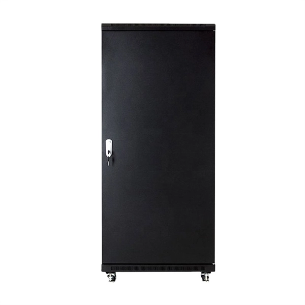
When selecting a distribution panel, prioritize models with adequate circuit capacity, clear labeling, UL certification, and compatibility with your electrical load requirements. For most residential or light commercial setups, a main lug or main breaker load center with space for future breakers. Choosing the right breaker and enclosure is essential for reliable electrical distribution at home or in light commercial settings. Read on. Electrical control panels and distribution boxes are the backbone of modern electrical systems. From powering homes and industrial facilities to supporting medium-voltage infrastructure, these enclosures ensure safe, efficient, and reliable power distribution. Smart electrical panels use AI and IoT to watch electrical power. The smart home market is growing fast. The DIY home improvement sector has seen a steady increase, with homeowners and renters opting to perform their own renovations and installations 3. This trend has directly boosted demand for products like. A distribution box, sometimes referred to as a panel board, distribution board, or breaker panel, is an essential part of electrical systems that makes it easier to distribute electricity throughout a structure. Dividing incoming electrical power from the main supply into subsidiary circuits is the.
[PDF]