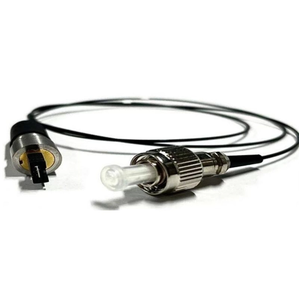
The connectors used in cold splicing typically consist of two parts: a ferrule and a body. The ferrule is a small, cylindrical piece that is designed to hold the fiber in place and maintain its alignment with the other fiber. Optical fiber cold splice technology is based on the use of mechanical connectors to join two fiber-optic cables. Get the wrong connector type, the wrong polish, or skip proper fusion splicing technique—and you're looking at elevated signal loss, increased back reflection, and a. Fiber optic joints or terminations are made two ways: 1) splices which create a permanent joint between the two fibers or 2) connectors that mate two fibers to create a temporary joint and/or connect the fiber to a piece of network gear. This is essential for extending network reach, repairing breaks, or connecting cables in data centers and telecom infrastructure. The goal is to align the microscopic glass cores (typically. In this guide, we cover the basics of fiber optic splicing, how to perform splicing using two different methods, and finally some best practices to perform good fiber splicing. What is Fiber Optic Splicing and Why is it Needed? – #1.
[PDF]
The QSFP+ module is designed for 40GBASE Ethernet throughput up to 10km over single-mode fiber (SMF) using a wavelength of 1310nm via duplex LC connectors. This transceiver complies with QSFP+ MSA and IEEE 802. 3ba 40GBASE-LR4 and OTU3 C4S1-2D1 standards. The Cisco 100GBASE Quad Small Form-Factor Pluggable (QSFP) portfolio offers customers a wide variety of high-density and low-power 100 Gigabit Ethernet connectivity options for data center, high-performance computing networks, enterprise core and distribution layers, and service provider. An Optical Transceiver is a critical optoelectronic component that facilitates seamless electro-optical (E-O) and photo-electric (O-E) conversion within fiber-optic networks. Cost-effective active optical components Rich experiences of producing and exporting ZION provides a range of high-quality, independently verified active optical components suitable for diverse settings, from large venues to small businesses. Their wide product selection caters to specific. Explore how AI clusters are reshaping network architecture, from XPU-centric design to multi-plane scalability, and learn how 800G modules enable high-performance, low-latency interconnects for modern AI data centers. In the design of AI computing clusters, Scale-Up and Scale-Out have different.
[PDF]
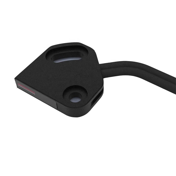
Compare products based on your own technical specification criteria. How does our search work? With MEET OPTICS search you get direct access to our database of thousands of optical components from providers worldwide. Prices and product specifications directly listed from optical component. The passive optical components market is projected to grow from USD 64. 8 billion in 2025 to USD 210. Optical Cables will dominate with a 48. The Passive Optical Components. These components function by transmitting, reflecting, splitting, or redirecting optical signals without the need for active electrical circuits. Common examples of passive optical components include optical fibers, optical splitters, couplers, and multiplexers. These components are essential in. A socket specifically developed for virtual production. Radio Receiver transmits tracking data from all connected Antilatency radio sockets to the target program on the PC. 6% during the forecast period. Passive components are the foundation stone of optical network systems. Most of. VIPER™ is the fastest, most accurate electromagnetic tracker in the world. With its sleek, small size, continuous tracking data of rates up to 960 frames per second, and latency as low as one millisecond, VIPER offers scaled-up capability in a scaled-down package. With added Fly True Technology.
[PDF]
Typically, an optical circulator consists of three main parts: wave plates, Faraday rotators, and birefringent crystals. When light enters the circulator, it is split into two beams with orthogonal polarization states. An optical circulator is a non-reciprocal device that directs light signals sequentially between multiple ports. You can think of it as a traffic controller for light, ensuring signals flow in one direction without interference. Unlike optical isolators that block reflected light, a circulator routes optical signals in a specific order — typically Port 1 → Port 2 and Port 2 →. An optical circulator is a three- or four-port optical device designed such that light entering any port exits from the next. This means that if light enters port 1 it is emitted from port 2, but if some of the emitted light is reflected back to the circulator, it does not come out of port 1 but. Optical Circulators are crucial components in modern optical communication systems, enabling the efficient routing of optical signals between different ports. In this comprehensive guide, we will explore the definition, basic principles, and importance of Optical Circulators, as well as their. The optical circulator is a fundamental device, acting as an advanced traffic controller that provides strict directional control over light signals within the network architecture.
[PDF]
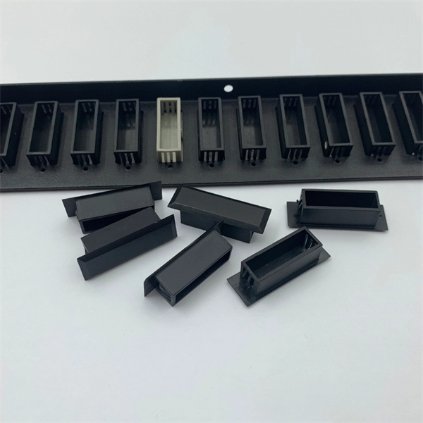
A fiber array (FA) is an arrangement where a bundle of optical fibers or a fiber ribbon is mounted onto a substrate with predefined spacing, typically using a V-groove baseplate. In optical communications, a fiber array mainly consists of a baseplate, a pressure plate, and optical. Fiber Arrays (FAs) are foundational components that enable this alignment by organizing multiple optical fibers into a compact and highly accurate format. Whether integrated into planar lightwave circuits (PLCs), optical switches, or high-speed transceivers, FAs play a vital role in ensuring. What is a Fiber Array (FA)? A Fiber Array, commonly abbreviated as FA, is a critical interface component in Silicon Photonics (SiPh) packaging, Photonic Integrated Circuits (PIC), and Co-Packaged Optics (CPO) architectures. It is responsible for efficiently coupling "external optical fibers" with. Fiber arrays, also known as fiber-optic arrays or fiber array units, are crucial components in the field of photonics. These arrays can be one-dimensional or two-dimensional, consisting of optical fibers that are often arranged at the end of a fiber bundle. What is a Fiber Array? A fiber array is an optical device that aligns and secures a bundle of. and data center applications. Often, such an array is formed only for the very end of a bundle of fibers, rather than over the whole fiber length. The purpose of such an array is typically either coupling light from.
[PDF]
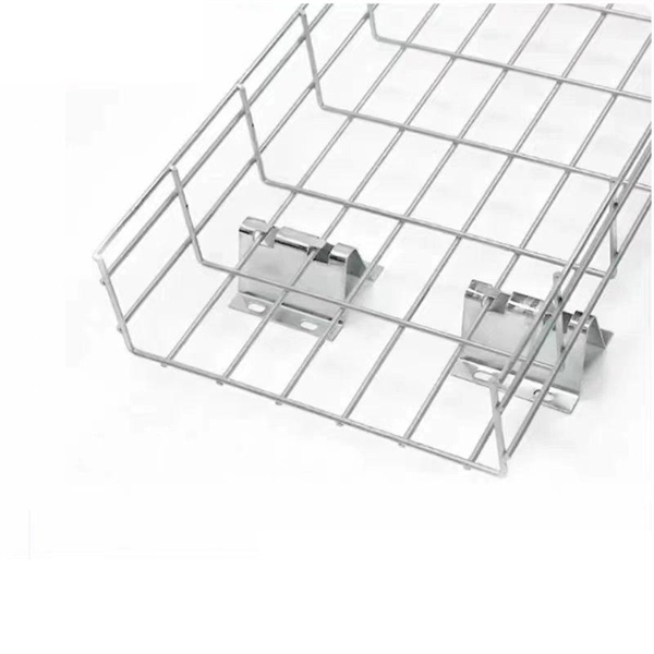
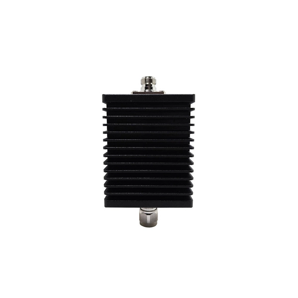
Pricing (USD) Filter the results in the table by unit price based on your quantity. Heat Dissipation Enclosures, Boxes, & Cases are available at Mouser Electronics. PTC heater HG 140 60 W used for preventing the formation of condensation and to enure that the temperature does not drop below a specified minimum. Heating fan VL 031 150W from VEMARK with power 150W and supply voltage 230VAC. Choose Duct Board - Sheets / Cases / Pallets for fabrication, Square & Triangle Distribution Boxes for branching, Supply & Return Plenums for equipment. Heat sinks are thermal management components designed to dissipate heat from high-power electronic devices and prevent overheating. Their core function is based on the principles of conduction, and convection, transferring heat from a heat source—such as a CPU, power transistor, or BGA package—to. Electronic Project Box Heat Dissipation PCB Aluminum Enclosure Shielded Instrument Cooling Case Split Power Junction Box Electrical Distribution Boxes 33x114x150mm EASY TO INSTALL: Instrument cooling box is designed in a split structure, with clear structure and complete accessories. It is easy to. 1. Customizable various frequency conversion cabinets 2. energy-saving transformation projects 4. Develop customized programming 5. Explosion-proof cabinet 7.
[PDF]
There are several different physical mechanisms that can be used to amplify a light signal, which correspond to the major types of optical amplifiers. In doped fiber amplifiers and bulk lasers, stimulated emission in the amplifier's gain medium causes amplification of incoming light.OverviewAn optical amplifier is a device that amplifies an directly, without the need to first convert it to an electrical signal. An optical amplifier may be thought of as a without an, or one in which. The principle of optical amplification was invented by on November 13, 1957. He filed US Patent US80453959A on April 6, 1959, titled "Light Amplifiers Employing Collisions to Produce Population Inversions".
[PDF]

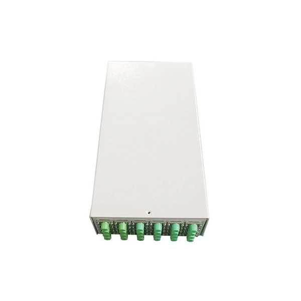
The main components of a splice box are the splice cassette that picks up the fibers and their reserves, and the front panel which contains different connectors for transmitting signals via copper or fiber optic cables. A splice box (also known as splice distributor) is a housing in which fiber optic cables begin or end. Fiber optics are fanned out in splice boxes that are situated at the end of fiber optic transmission paths. It typically consists of two parts: an outer housing and an internal structure. In this response, we will focus on the. The FSB series of indoor wall mount enclosures are designed for centralized splice-only applications. These boxes are well suited as optical cable splice collection points for DAS (Distributed Antenna Systems), MTU (Multi-Tenant Unit) commercial business applications, and MDU (Multi-Dwelling Unit). Fiber optic splice closures permanently connect two fiber optic cables together and have a splice that protects the components. The optical cable connection part, that is, the optical cable joint, is the part that protects the connection between two or more optical cables by the optical cable. Splicing refers to the permanent connection of two optical fibers to form a continuous optical connection.
[PDF]
Fiber testing is the process of verifying the performance of optical fiber cabling. This process includes a range of tests and measurements such as insertion loss, optical return loss, and fiber length. It encompass.
[PDF]

The PV combiner box test in solar power systems is a fundamental procedure that verifies the accuracy of string connections and the electrical current flowing to inverters. This test helps prevent energy losses while optimizing system performance. ance cables by combining strings at the array locat ciency, reliability and safety in solar energy systems. They enable centralized management in large-scale and remote installation ity), equipment aging, and poor installation practices. MapperX performs this critical test professionally. This guide provides a step-by-step method for safely testing energized PV strings to locate intermittent ground faults using reliable tools and procedures. What Is an Intermittent Ground Fault? An intermittent ground fault is a temporary electrical connection between a current-carrying conductor. A PV combiner box, often referred to as a solar combiner box, is a critical component in solar energy systems. This device plays a significant role in both residential and commercial solar installations, particularly when. We do a lot of solar PV and renewable energy asset inspections here at HelioVolta and SolarGrade! Every time we visit a site, we use the SolarGrade platform to guide our workflow and document our findings. Missing/Improper Label Improper labeling can be a risk to personnel and should conform to.
[PDF]

The fastest way to test a fluorescent tube is with a multimeter set to continuity mode. Each end of the tube has two pins connected by a thin filament inside the glass. If either filament is broken, the tube is dead. The whole test takes about 30 seconds per tube once you know what. This is a complete guide for testing a fluorescent light bulb with a multimeter. You don't have to be an expert in electrical work. This process measures electrical resistance to determine if the tube has suffered an internal failure before replacing the bulb or investigating the ballast. This guide provides a comprehensive understanding of the process, equipping you with the knowledge and. To test a fluorescent light bulb, observe any of the following: flickering light, low brightness, buzzing sound, delayed start, and fading color and light variation. Turn off the power to the circuit that powers the fixture and keep the leads steady to ensure accurate readings. Multimeters provide. How to Test Light Bulbs & Fluorescent Tubes with a Multimeter (Continuity Check) Is your lamp or fixture failing to light up? Before you buy a new bulb, you need to confirm if the bulb or tube itself is the problem! A simple continuity check using a multimeter can instantly tell you if the filament.
[PDF]

Regularly testing fiber optic cables helps minimize network downtime, lengthens the network's longevity, reduces maintenance requirements, and helps support network reconfiguration and upgrades. Fiber optic testing ensures the performance and reliability of fiber optic networks. Key tests include: Effective fiber testing utilizes advanced tools such as Optical. Fiber optic testing for continuity is crucial in ensuring that light transmits through fiber optic cables without interruptions, safeguarding seamless data transmission. This guide talks about the primary methods and tools for effective continuity testing in fiber optic cable networks. Insertion loss testing confirms whether the cable meets design loss budgets. OTDR testing identifies events along the fiber length, including: OTDR is essential for long-distance FTTH feeder and distribution cables. After the cables are installed and terminated, it's time for testing. For every fiber optic cable plant, you will need to test for continuity, end-to-end loss and then troubleshoot the problems. If it's a long outside plant cable with intermediate splices, you will probably want to verify the. We'll explain why it's vital to test fiber optic cables, the three most popular methods, and when you should use them. Why Testing Fiber Optic Cables Matters? Regular testing of fiber optic cables is not just a preventive measure; it's an.
[PDF]

This guide will walk you through the process of checking photo sensors using a multimeter, covering various types of photo sensors, the necessary tools and safety precautions, and the specific measurement techniques involved. Knowing how to effectively use a multimeter to test photo sensors can save you time, money, and frustration when dealing with malfunctioning devices. more What is a Voltage Divider? | What is a Voltage. Before replacing the sensor or fixture, it's efficient testing it first, With a few tools and a step-by-step process you can find whether your outdoor lighting control system is working as intended or if the problem lies elsewhere. In this complete guide from Lead-Top, a global leader in photocell. In this blog post, we explain step-by-step how to troubleshoot a sensor with a digital multimeter (DMM). Here are the steps: Troubleshooting a sensor measurement failure requires mechanical tools to uncover the protective shields or components so you can reach the sensor in question. Always follow the manufacturer's instructions for the sensor and multimeter. Ensure the sensor is properly connected to the multimeter and. A multimeter is an indispensable diagnostic tool for anyone working with electronics, electrical systems, or indeed, sensors. It's a versatile device capable of measuring voltage, current, and resistance, providing crucial insights into the health and functionality of electrical circuits and.
[PDF]

Fiber optic connector pull test demonstration with real-time insertion loss monitoring. We use an optical loss tester to track signal stability every second while controlled tension is applied to the fiber. more. Fiber optic cable is surprisingly strong, durable and pliable; however, several best practices should be followed to ensure a successful cable installation. The below article explores the best practices and tools commonly used to pull fiber optic cable. The Future Ready Solutions Tools & Test. NEOFIBO TFTM-100N Vertical Fiber Optics Cable Tension Testing Machine The Cable Tensile Testing Machine is a precision mechanical measuring instrument designed to evaluate the tensile strength and elongation properties of various cables, wires, and fiber optic assemblies. Most fiber damage does not come from normal operation after the system is live. It happens during installation, when excessive pulling force, tight bends. Fiber optic connectors are designed to be connected and disconnected many times without affecting the optical performance of the fiber circuit. Optimal performance can be achieved by following the correct process for termination of the fiber circuit—a task which requires the use of a wide range of. The Fluke Networks JR-LEV-1 JackRapid Punch Down Tool is a cable termination tool that is designed to give technicians maximal efficiency in cable maintenance.
[PDF]

