
This Distribution Commissioning Manual is intended for use when undertaking testing and commissioning activities of electrical apparatus on Western Power's distribution network. It's recognised that equipment procured by Western Power changes over time, therefore this manual does not aim to. Furthermore, this handbook seeks to fully provide one with knowledge on electrical tests, check lists, testing criteria, test forms, circuit connection diagrams needed for testing, Documented for review and future comparison with the outcomes of maintenance tests are the test procedures and test. offices throughout Peninsular Malaysia. TNB's core activities are in generation, transmission and distribution of electricity wh ers electricity supply to the customers. Retail Division is responsible for the downstream retail operations conducted through a network of 14 states which involves.. The supplier shall indicate makes and types of offered isolator in GTP. The Switch disconnector to e provided in the Distribution Box will be as per Emplo e as per IS:13411 (amended. vernmental platform in the Asia-Pacific region. The Commission promotes cooperation among its 53 member States and 9 associate members in pursuit of olutions to sustainable development challenges. ESCAP is one of the lder, provided that the source is acknowledged.
[PDF]

The modern electric power transmission, control, and distribution network demands precision, reliability, and advanced data analytics for each step in its operation. As a Relay Protection Engineer, your work in relay testing and commissioning is critical to ensuring system safety and continuity. In. The testing and verification of protection devices and arrangements introduces a number of issues. This happens because the main function of protection devices is related to operation under fault conditions so these devices cannot be tested under normal operating conditions. Protection relays are critical for detecting faults, initiating protective actions, and isolating faulty sections of the. Relay systems protect high-voltage equipment and transmission lines to ensure safe, stable systems. Although failure of a protective relay system may have severe local or regional impacts, most protective relay systems are not required to operate to prove they are in working order. Ensuring that. The strategies available to remove these risks are many, but all involve some kind of testing at site. Modern power systems are becoming increasingly complex, with growing demand, integration of renewable energy, and rising expectations for reliability and safety. In this environment, protection relays serve as the guardians of.
[PDF]
Key techniques include using bonding agents, saw-cutting, re-pouring concrete, mechanical connectors, and epoxy injection. Conventional methods like epoxy grout injection can address cracks effectively. Learn how to prep and bond a next-day concrete pour to repair a cold joint. This guide walks through practical surface prep, bonding methods, and timing so you can create a strong, durable joint. You'll gain actionable, plain-language steps and tips you can apply on real job sites. Identify cold. A cold joint is a common imperfection in concrete construction, occurring when fresh concrete is poured next to a section that has already begun the setting process. This discontinuity prevents the two pours from chemically integrating into a single monolithic unit, creating a weak plane within the. A cold joint in concrete is an area or surface with a structural discontinuity caused by the delayed concrete pouring between two layers of concrete. This issue compromises the structural integrity and durability of the concrete. This transition from a plastic or fluid state to a semi-solid state creates a discontinuity.
[PDF]
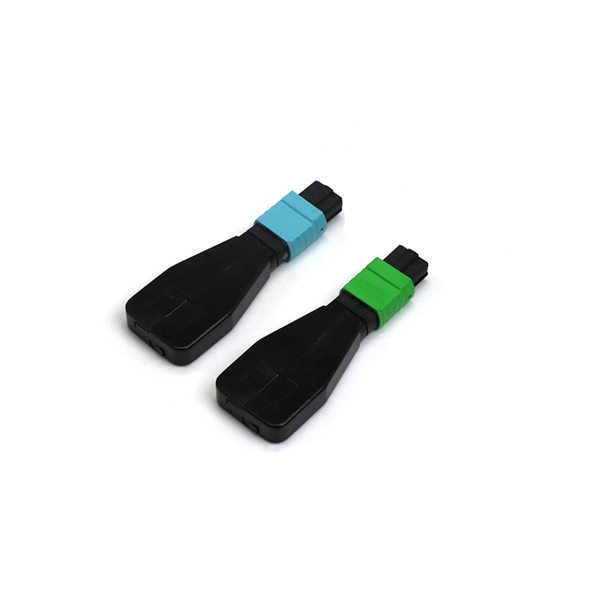
GPON Xpert is a modular tool designed for R&D, laboratory and field application engineers engaged in the development, testing and deployment of G-PON standard-compliant solutions. The GPON Xpert multi-layer analyzer is a unique protocol analyzer for G-PON products. GPON Xpert verifies the. Fiber Optical Test offers a comprehensive line of PON-specific testing solutions designed for fiber network installation, activation, and maintenance. Passive Optical Networks (PON) demand precise testing technologies tailored to their unique architecture and performance requirements. Fiber Optical. OLP-88 TruePON tester is an innovative tool using GPON data analysis technology. It is the ideal test unit for field technicians dealing with GPON network service activation and for support teams in charge of resolving service complaints and identifying the sources of issues. GPON Xpert verifies the. TraceSpan's non-intrusive solutions empower broadband access networking with deep protocol analysis across all communication layers Gain complete visibility and deep understanding of your access network elements and the traffic running through them, powered by independent testing tools and.
[PDF]

First, inspect the optical module appearance for physical damage, cracks, missing components, poor solder joints, or burn marks. Next, compare voltage, resistance, and waveform parameters between a normal it and the suspected faulty one, both in powered and unpowered states. As core components of optical communication systems, the proper installation and use of optical modules directly impacts network stability. This article systematically identifies common anomalies during optical module installation. However, during installation and daily operation, various issues may arise. The following will introduce the causes of various problems and how to deal with them. Optical module method/step 1. During the test, the value of the module I BiasADC is 0, and the TXLOP-ADC and. These compact devices convert electrical signals to optical signals and vice versa, enabling data transmission over fiber optic cables. While generally reliable, failures do occur, leading to frustrating downtime, performance degradation, and costly troubleshooting. This comprehensive guide details. Have you ever dealt with sudden network drops from faulty optical modules? Issues like this cannot only break communications, but they can really jeopardize business continuity.
[PDF]
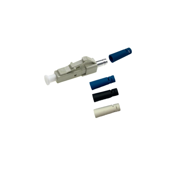
A fiber optic pigtail is a short length of optical fiber —typically 0. 5m to 2m—that has a factory-terminated connector on one end and bare fiber on the other end. The connector end is polished and tested under factory conditions, ensuring low insertion loss and high return loss. They are the bridge between fiber optic cables in the field and the equipment or patch panels that manage them. By combining factory-installed connectors with spliced bare fiber, pigtails ensure that network installers can create. The most urgent stage of the process is, in fact, separating fiber optic pigtail, also known as pigtail fiber or pigtail fiber optic cable. These short, pre-terminated cables play a vital role in terminating and splicing optical fibers, especially in complex fiber infrastructure such as data. Executive Summary: A fiber optic pigtail is one of the most commonly specified yet least understood components in structured cabling. Get the wrong connector type, the wrong polish, or skip proper fusion splicing technique—and you're looking at elevated signal loss, increased back reflection, and a. A fiber pigtail is a short optical fiber cable with a connector pre-installed on one end and a bare fiber on the other. The quality and.
[PDF]
United Rentals has low-pressure air testing equipment for rent, most commonly used to test for line acceptance or leaks in pipe joints and sewer line installation. For more. Air Testers install blower door testing equipment (big fans) to an external opening (typically a doorway) and will use this to pressurise or depressurises the building and test over pressure differentials Using thermal imaging, the tester will be able to identify air leakage points where warm air. Simple to Operate: The air ejector has no moving parts and no lubrication is necessary. After applying leak detection fluid along the seam, simply place the vacuum device over the area to be detected and open the air valve. Rugged Yet Lightweight: Our shockproof Vacuum Devices are built with. A pioneering approach to fabric air permeability measurement that releases a low-pressure pulse of air for realistic and accurate measurement of airtightness of buildings in seconds. A portable diagnostics fan that can help identify air leakage paths within buildings, helping to minimise. This is where you can browse products in this store. For more information, visit our resource. Airtightness tester s help make homes use less electricity by finding where air leaks are. When structures are less leaky, they need lower utility bills to heat or cool them. This savings makes buildings more environmentally friendly. By sealing tightly, pollution from outside cannot easily enter.
[PDF]