Integrated Power Services (IPS) is your power partner for operating reliability. We repair, rebuild to “like new” condition, and remanufacture electrical equipment. We also supply low- and medium-voltage circuit breakers, switchgear, transformers, and related parts, both new and obsolete. National. From sales to repair to field services, we support reliable energy solutions across clean and traditional power systems. Harnessing energy from clean and traditional sources, we deliver tailored solutions for reliable and efficient power generation systems. Whether it's electromechanical equipment. Integrated Power Supply provides a stable and reliable AC and DC power supplies against all AC mains variations or interruptions. Enhance safety in train operations (by avoiding blanking of signals). It consists of the following modules: The. Independent Power Setup: Critical instruments or instrumentation systems are equipped with dedicated uninterruptible power supplies (UPS). This ensures continuous power during unexpected outages in the main power grid, safeguarding data integrity and preventing equipment shutdown. For instance. At their base level, residential, commercial, and industrial automation complexes must incorporate a wide range of security, safety, and emergency communications systems for insurance requirements and local building codes, and to receive a certificate of occupancy.
[PDF]

This section provides an overview for optical power meters as well as their applications and principles. Our list of suppliers for that category contains 69 suppliers. Understand the Technical Background To support your technical evaluation, this section includes links to authoritative encyclopedia articles for in-depth verification of the underlying physics, technical issues and techniques. Market Forecast By Type (Thermal Detectors, Photo Detectors), By Instrument/Product Type (Benchtop Meter, Portable Meter, Virtual Meter, Optical Wavelength, Hand-Held Meter, Others), By Detector Type (InGaAs (Indium Gallium Arsenide), Germanium, Silicon, Others), By Power Range (High, Medium, Low). This section provides an overview for optical power meters as well as their applications and principles. Here are the top-ranked optical power meter companies as of May, 2026: 1. Novanta. Photon Systems, Inc. designs, develops, manufactures and markets deep ultraviolet lasers and incoherent sources, instruments based on these sources, and optical and electro-optical accessories for a broad range of applications primarily within the. All of EXFO's modular (IQS line) and benchtop power meters are built for top performance and pinpoint accuracy, and the various models offer a mixture of features and specifications to suit various test setups. Fast, accurate, flexible power. © Copyright© Santec Holdings Corporation.
[PDF]
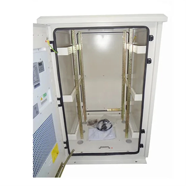
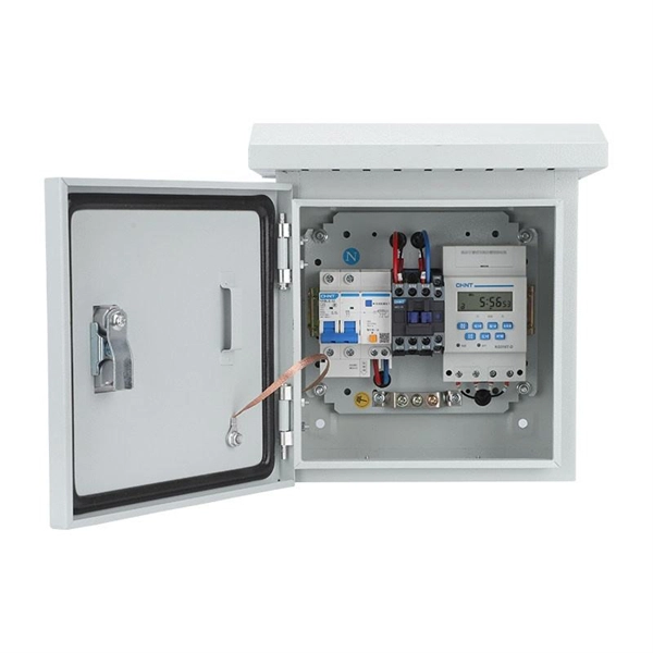
This AutoCAD DWG file includes a complete Single Line Diagram (SLD) of a Distribution Board, showing circuit breakers, wiring connections, and load distribution for lighting, power, and mechanical systems. Knowledge of the basic electrical power distribution system and its components will help the operator understand the importance of electrical power distribution systems. Failure-free power e. Overlapping protective zones a. Protective relays A single, or one-line. A power distribution box (also called PDU or distro) directs electricity from a main source to multiple circuits. It acts like a hub or traffic controller, managing power flow to different areas or devices. Key components include circuit breakers, fuses, bus bars, and internal wiring for safety and. Check electrical parameters: First understand the basic electrical parameters of Distribution box so that you can have a general understanding of the capacity and performance of the distribution box. Analyze the incoming line part: Determine the incoming line source of the distribution box and. ndards and conformity assessment activities in the United States. ANSI facilitates and promotes voluntary consensus standar rty or economic loss due to fire, electrical and related hazards. Now, let's look at how consumers use electrical power. What is a Electrical Power Distribution System? 1. Power supply is received from LT panel and distributed to the outgoing feeders for utilization.
[PDF]
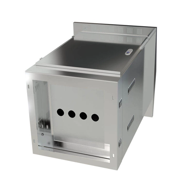
BSLI is an original equipment manufacturer (OEM) of custom electrical power distribution products. BSLI guarantees its customers fast, personalized service, quality components, and custom-designed equi.
[PDF]
From the transformer, power goes to the busbar that can split the distribution power off in multiple directions. The bus distributes power to distribution lines, which fan out to customers.OverviewElectric power distribution is the final stage in the. Electricity is carried from the to individual consumers. Distribution connect to the transmission system an. Electric power distribution become necessary only in the 1880s, when electricity started being generated at. Until then, electricity was usually generated where it was used. The first power-distri. Electric power begins at a generating station, where the potential difference can be as high as 33,000 volts. AC is usually used. Users of large amounts of DC power such as some,. Primary distribution voltages range from 4 kV to 35 kV phase-to-phase (2.4 kV to 20 kV phase-to-neutral) Only large consumers are fed directly from distribution voltages; most utility customers are connected to a transformer.
[PDF]
Built on Huawei's unified software platform and equipped with high-performance fully programmable chips, they deliver abundant features including Service Roam, VXLAN and iFlow, helping customers build high-quality campus bearing networks for the all-wireless era. Leveraging the Service. CloudEngine S5735-S-V2 switches support simplified operations and maintenance (O&M), and flexible Ethernet networking. It also provides enhanced Layer 3 features and mature IPv6 features. For example, it can be used as an access or. CloudEngine S5736-S series switches are next-generation standard all-optical GE access switches that provide 24-port and 48-port models, and provide four 10GE ports and one extended slot(optional). CloudEngine S5736-S series all-optical GE access switches are developed based on next-generation. Comprehensive analysis of Huawei's revolutionary optical switch innovations for 2025, including data center all-optical switching, silicon photonics integration, quantum-compatible switches, and 5G-Advanced network solutions. The port supports the PoE function. It sends and receives service data at 1000 Mbit/s or 10 Gbit/s.
[PDF]
Silicon photonics is transforming AI computing by enabling energy-efficient, high-speed data transmission. Discover how optical interconnects present a possible solution to the data center energy crisis and drive sustainable innovation. Lam Research is setting the agenda for the wafer fabrication equipment industry's approach to a silicon photonics revolution, driving the breakthroughs in Specialty Technologies that will enable sustainable AI scaling through precision optical manufacturing. The artificial intelligence boom has. y with vastly reduced energy con-sumption by integrating optics deeply within computing sockets. We present the design and characterization of a dense wavelength-division multiplexing (DWDM) SiPh transceiver chip, featuring a unique architecture in the multi-FSR regime and targeting a shoreline. Silicon photonics is becoming a critical enabler of AI and HPC, breaking the limits of electrical interconnects in bandwidth, distance and power efficiency. Co-packaged optics (CPO) builds on silicon photonics, with SiPh transceivers as the integration platform and CPO as the packaging architecture. Silicon Photonics emerges as the solution to this predicament, replacing electrons with photons—the fundamental particles of light—to race across familiar silicon-based chips, promising a revolution in computing and communication. This isn't just about increased speed; it's about a profound impact.
[PDF]

Select the correct wavelength and set your reference. You measure optical power in dBm or insertion loss in dB. Consistent procedures ensure accuracy. Measure total signal loss from fiber, connectors, or splices. Optical fiber attenuation is the attenuation per unit length of optical fiber, and the unit is dB/km. When connecting two optical fibers, there will be loss inside any connector or joint. Consistent measurement techniques. While optical power meters are the primary power measurement instrument, optical loss test sets (OLTSs) and optical time domain reflectometers (OTDRs) also measure power in testing loss. TIA standard test FOTP-95 covers the measurement of optical power. Optical power is based on the heating power. Light Source: The CMA5 Series Light Sources provide an economical and stable laser source for use in point-to-point attenuation measurement. They feature a rugged design, built to withstand the difficult testing environment of fiber optic cable installation and maintenance. The CMA5 Light Sources. When talking about optical measurements, wavelength basically means how far a wave pattern repeats itself, usually measured in nanometers (nm). Commonly, a power meter on its own is used to measure absolute.
[PDF]
Whether you're building a commercial setup or upgrading an industrial plant, proper cable tray installation ensures neat wiring, safe access, and easy maintenance. But before you lay the first tray or clamp down a single cable, you need a solid plan. This guide breaks. This method statement covers the site installation of the cable tray & ladders and the requirements of checks to be carried out. The Cable Tray system is installed in electrical rooms, plant rooms, and service corridors. This guide breaks down the process step by step. This process is integral to determining the optimal arrangement and configuration of cable trays, which are essential for routing and supporting electrical cables within buildings and. 1. 0 This method statement will serve as a minimum guideline to carry out the Cable Tray Installation activities for commercial buildings, plants and refineries in accordance with Project Drawings and Specifications. This document outlines the key requirements for cable tray layout, installation, and fireproofing in industrial and commercial environments. Route. Below is the detailed cable tray installation method statement not only for cable tray but also applicable for GI ladder and trunking for indoor and outdoor applications and in service rooms like pump rooms, electrical rooms and plant rooms etc. All materials intended for cable tray, ladder and.
[PDF]
We are a one-stop shop for top-notch Electrical Cable Tray in Brazil. Our cable trays are manufactured from robust materials and rigorously tested to ensure they can withstand even the most demanding environments. With 8,500 m² of built area, Eletropoll Trays offers to the market electrical ducts, profiles, beds, accessories, fasteners and support, busbars for lighting and related products. The Tray Unit has achieved excellent certifications. We, one of the top Electrical Cable Tray Manufacturers in Brazil, offer a wide. If you are searching for Cable Tray in Brazil, Brilltech Engineers Pvt. is a trusted brand that you can rely on. We have a well-equipped manufacturing unit with all the advanced resources to cater to your distinct requirements as per your industry preferences. Moreover, our focus on maintaining high quality and. EAE Electric started the production and use of busbar trunking systems in Turkey in the 1970s. Support systems can be manufactured with thicknesses from 2mm to 6mm with Pre-galvanized, Hot Dipped Galvanized, and Painted coatings in various options. EAE cable trays are produced on automatic. Chalfant Ladder Cable Tray Systems are ideal for indoor and outdoor cable management. They provide reliability, ease of installation, and cost savings both initially and long term. With multiple finishes available, we have the perfect ladder tray for any environment. screwless connections.
[PDF]

This article will introduce passive optical networks (PON), in which we will introduce everything about OLTs, ONTs, ONUs, and ODNs, including their operation principles and functions. PON (Passive Optical Network) refers to a fiber optic network built using a point-to-multipoint topology and fiber. Active Optical Networks (AON) and Passive Optical Networks (PON) make FTTH broadband connections possible. To date, most FTTH deployments in planning and deployment have used PON to save on fiber costs. PON has attracted much attention in recent years due to its low cost and high performance. There are no specific requirements for this document. This document is not restricted to specific software and hardware versions. The information in this document was created from the devices in a. OLT, ONU, ONT, and ODN are key components and acronyms used in Passive Optical Network (PON) architecture, which is a popular technology for delivering high-speed broadband services. This technology is widely used in fiber-to-the-home (FTTH) and fiber-to-the-premises (FTTP) deployments. In contrast to AON, multiple customers are connected to a single transceiver by means of. An Optical Distribution Network (ODN) serves as the bridge in a Passive Optical Network (PON), transmitting optical signals from the Optical Line Terminal (OLT) to the Optical Network Unit or Terminal (ONU/ONT), thus linking a service provider's core network to end-users (residential or business).
[PDF]

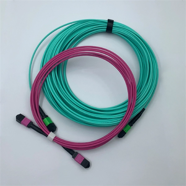
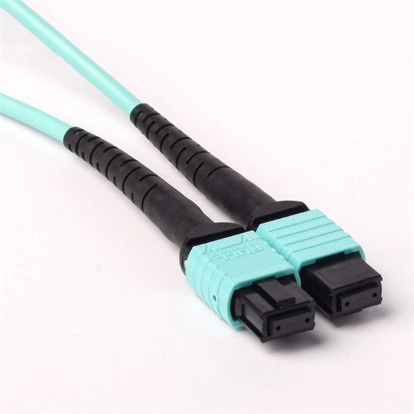
Optical fibers or fiber cables can be used for transmitting optical power from a source to some application. In their served areas will be power generating stations, alternative energy sources (solar, wind, geotherman, etc. ), substations for distribution and microgrids. These networks must be monitored and managed to ensure reliable power for the utility's customers. For monitoring and managing networks. Low voltage cables are mounted on poles in the "telecom space," well below power cables. Optical power ground wire (OPGW) is an electrical power ground with fiber optics in the center of the conductor. That conversion can be done with a photovoltaic cell. The Commission, on June 22, 1965, noting that the increasing demand for underground electric and communication facilities in California has brought about substantial increases in the construction of such facilities, and that it appeared it may be desirable, pursuant to Sections 761, 768 and 8056 of. One choice is optical power ground wire (OPGW). This conductive cable is run at the top of the tower or pole to be the ground conductor and protect the power cables from lightning. The fiber. While fiber optics is essential for internet service providers to deliver higher bandwidth and faster transmit speeds, there are also many crucial benefits of fiber optics in energy and power. Utility companies face various challenges as they work to deliver reliable energy to homes and industries.
[PDF]
Housing Integrity: Cracked, melted, or physically broken outer casings. Electrical Failure: Severe internal burn marks or "fried" traces that prevent a safe rebuild. Completeness: Units that have been scavenged for internal parts or are missing proprietary hardware. This document describes how to identify, isolate, and troubleshoot symptoms of hardware failures on Catalyst 9600 Supervisors and Line Cards. There are no specific requirements for this document. The information in this. If the switch has rebooted unexpectedly, you can follow the steps to troubleshoot the hardware. If your core looks different. This topic covers the steps for troubleshooting bootup, crash, network, software, and audio issues related to the Q-SYS Core 110f processor and Cinema Core 110c processor. It details what information to collect post-event to help identify the root cause. Requirements and Components Used Requirements: None specific to hardware/software versions. Lab. Hardware faults on CE switches include power supply faults, fan faults, card power-on failures, unexpected card restarts, abnormal optical module status, and abnormal interface status. The following information helps you quickly locate hardware faults. Common Causes of Power Supply Faults Common.
[PDF]

Key finding: This paper develops analytical models and design procedures of ultra-wideband Wilkinson power dividers using linearly tapered transmission lines (TTLs) which provide size reduction and broadband performance. Read more. Power dividers are the passive electronic equipment used for splitting the power. They are now being employed in a variety of communications applications such as telephonic, antennas configurations, mobile connectivity, internet technology, & optics, etc. They come up with very low loss, operate at. RF and microwave power splitters and dividers create two copies of the same signal, while ideally preventing crosstalk between the outputs. Doing this with minimal loss while maintaining signal integrity is a challenge. In this article we explain how power splitters work and what the tradeoffs are. The rise of wireless connectivity requirements for applications such as Internet of Things (IoT), cellular, and automotive electronics is resulting in systems that are increasingly using RF signals, components, and subsystems. Often, designers need to direct these signals to more than a single. A power divider is a passive electronic device used in radio frequency (RF) and microwave applications to split an input signal into multiple output signals with equal or specified power levels, while maintaining impedance matching to minimize signal reflection and loss. How can power dividers.
[PDF]
Diagram showing positive tip polarity on the left and negative tip polarity on the right. To read diagram: The center positive drawing on the left indicates that the center (also known as the tip) of the output plug is positive (+) and the barrel (ring) of the output plug is negative. The center positive drawing on the left indicates that the center (tip) of the output plug is positive (+) and the barrel of the output plug is negative (-). Symbol for a center-positive power supply. It is always good practice to test. The term positive terminal describes which of the two connection terminals on direct current (DC) equipment supplies or is meant to receive a positive electrical charge. DC power supplies always feature a positive to negative electron flow and always have a negative and positive terminal. Polarity. It is defined by the positive and negative terminals of a power source, such as a battery. Understanding polarity is essential because connecting a device to a power source with the correct. The rating plate of an Extra Low Voltage Power Supply (ELVPSU) shows various symbols and abbreviations. These represent critical information about the supply's ratings, class, polarity, and other safety details. The polarity symbol indicates if the centre (or tip) of the output plug is positive (+).
[PDF]