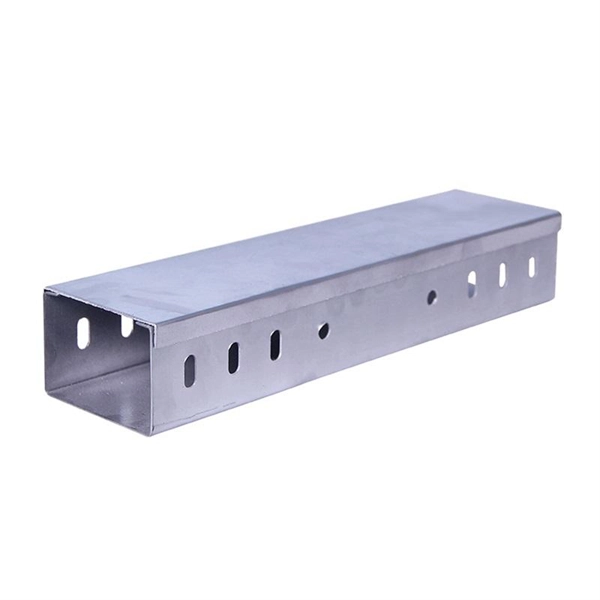
Cable Trays* — Max two 24 in. (610 mm) wide by max 6 in. (151 mm) deep open-ladder cable tray with channel-shaped side rails formed of 0. 54 mm) thick aluminum or min 0. In practice, cable tray dimensions are a system of interrelated measurements —width, depth, length, and material thickness—that directly affect cable fill compliance, heat dissipation, structural loading, and long-term expandability. From an engineering standpoint, cable tray dimensions are not. Perforated Cable Tray System expertly constructed from high-grade stainless steel, offering exceptional durability and resistance to corrosion. With side height 100mm. A properly designed and installed cable tray system will provide. Studs — Wall framing to consist of wood studs or channel shaped steel studs. Wood studs to consist of nom 2 by 4 in. Additional studs shall be used to completely frame. Best Size: Here, deep trays (75mm to 150mm) are used since power cables are typically thick and heavy. Data cables, such as your Wi-Fi or computer ones, are extremely sensitive. They do not get hot; however, they do not like to hang or sag. In case a data cable folds in an excessive manner, the. ect the minimum bend ra-dius for cables as they exit the bottom of the cable tray. A rung spacing of 6 to 9 inches (150 to 230 mm) is preferable when the cable tray cont d for instrumentation and control applications that require additional protec eferred to support and protect numerous small.
[PDF]
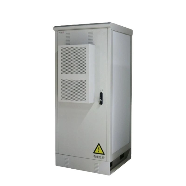
The proper installation of a distribution box involves placing it at the right height to ensure safety and convenience. 7 meters) high makes it easily accessible without the need to bend or stretch excessively. This height also safeguards the box from potential. MOUNTING HEIGHTS FOR ELECTRICAL DEVICES ELECTRICAL GENERAL NOTES NOTES: 1. ALL DIMENSIONS ARE CONSIDERED FROM FINISHED FLOOR AND, UNLESS NOTED OTHERWISE, SHALL NOT VARY. ALL DIMENSIONS SHALL BE COORDINATED WITH ARCHITECTURAL DETAILS AND MAY BE. Due to the long time interval between the embedding of the box and the installation and wiring of the box panel, the box shall be disassembled with the box cover (door) and the panel first, and marked for storage, so as to prevent the electrical components and the box cover (door) from damage or. Learn how to install a distribution box safely and correctly. Covers wiring, placement, standards, and expert tips for a compliant setup. It takes the incoming power and safely distributes it to different circuits throughout your building. In this documentation package, Duke provides comprehensive construction specifications in effect on July 1, 2021, to the Interconnection Customer. Interconneciton Customer shall reference these materials in the self-administered compliance program. Ground-mounted foundations should be 50 to 100 mm above ground level. When flused installed in the wall, the bottom is 1. 2m away from the ground.
[PDF]

A fiber-optic splitter, also known as a beam splitter, is based on a quartz substrate of an integrated waveguide optical power distribution device, similar to a coaxial cable transmission system. The optical network system uses an optical signal coupled to the. In modern FTTH (Fiber to the Home) and optical communication networks, three types of fiber distribution products are widely used: Splitter Distribution Box, ODF (Optical Distribution Frame), and Fiber Terminal Box. Although they all belong to the optical distribution and management system, their. These include the Optical Line Terminal (OLT), pivotal in initiating the fiber optic signal; the Optical Distribution Frame (ODF), which organizes and manages connections; and the Passive Optical Splitter (POS), responsible for dividing the optical signal to serve multiple premises. Additionally. Fiber splitters and fiber distribution terminals (FDTs) are integral parts of these networks, each serving distinct functions. While both facilitate signal distribution, they possess unique features and applications. Delving into the main differences between fiber splitters and fiber distribution. In the backbone of modern Fiber-to-the-Home (FTTH) networks, optical splitters serve as the unsung heroes that enable cost-efficient connectivity for millions of subscribers. By dividing a single optical signal from a central Optical Line Terminal (OLT) into multiple outputs for Optical Network.
[PDF]
Wall-mounted fiber distribution frames are typically designed as box-like structures, ideal for locations with fewer cables and fiber cores. Whether you're building a central office, data center, or FTTx distribution network, understanding the right ODF. FDF, or Fiber Distribution Frame, is a key component used for the termination, utilization, and management of optical cables between wiring rooms and equipment rooms. In structured cabling systems, ODFs are suitable for horizontal cabling between equipment or their terminations, as well as. A distribution boxes is an essential device that manages the safe and efficient flow of electrical power throughout different areas of a building or facility. It is commonly used in homes, offices, and industrial settings to control and protect electrical circuits. Understand its role in electrical systems and safety.
[PDF]
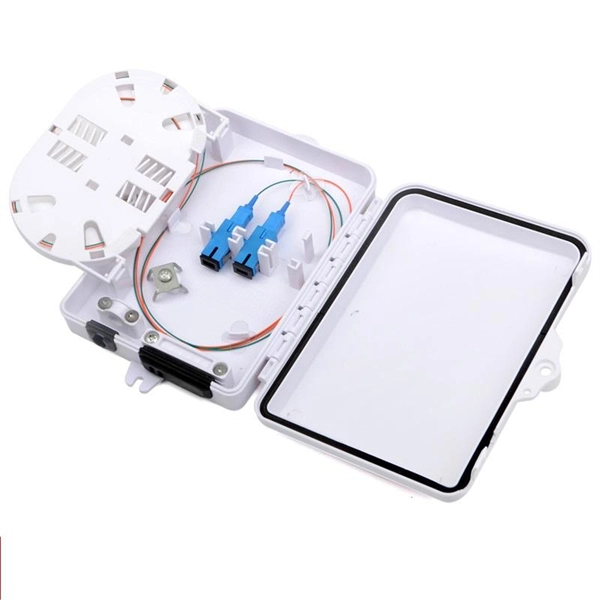
Feature -- 2 ports optical fiber distribution box is used for the fusion splicing, splitting, wiring transmission and other functions of the optical transmission terminal. It can effectively terminate, protect and manage the optical cable. It is a necessary equipment in network. Fibertech Misr supplies all components of fiber optic networks of fiber optic cable, patch cord, Pigtail, Adaptor, closure, Connector, media converter, over 11 years, the implementation of Telecommunications projects, Training for Welding, Measuring,FTTH,GPON, SDH,DWDM,CCTV,IP TV. Explore high-capacity Fiber Optic Patch Panels, Termination Boxes, and ODF solutions for robust telecommunications infrastructure. Our expertise, high-quality products, optimal cost/performance ratio, and time-saving approach set us apart from the competition. All Rights reserved. © 2026 COMTEC-SOL. COMtec Integrated Solutions, we are a leading manufacturer and vendor of cutting-edge Telecom infrastructure solutions, specializing in both Copper and Optical Fiber technologies. It's perfect for use in data centers and other telecommunications applications, and it's sure to provide you with the excellent performance that you need. Streamline your fiber connectivity with our premium Fiber Optic Patch Panels and ODF systems. Designed for reliability and ease of use, our rack-mount and wall-mount solutions provide the perfect environment for splicing, terminating, and managing your critical fiber optic connections.
[PDF]

A ladder type cable tray tee is a fitting used to create a branch in a cable tray system, allowing cables to be routed in three directions. Its "T" shape provides a secure and efficient way to split cables from a main tray into two separate paths, ensuring organized and flexible. A cable tray tee and tee cover are components used in cable management systems to support and protect electrical and data cables. Here's a brief explanation of each:. Rigid steel cable tray tee fitting with zero tangent, safety bottom, and full accessory support. ventilation to heat producing cable such as power communication and other with the same or different width of the cable run. All fittings are available in sizes and types corresponding to the straight cable tray sections. These fitting are including: elbow, horizontal cross, vertical inside. NOTE : Equal or un equal tees can be supplied. When ordering state widths W1xW2xW3.. Office: 147/22 Nguyen Sy Sach Street, 15 Ward, Tân Binh Dist, HCMC,VN. Is it possible to connect 2 cabletrays with a "branch piece (left picture)" instead of a "tee (right picture)". The tee has 3 connectors, the branch piece only has 1 connector. I would like to ajust the "Type properties -> Fittings -> Tee" with the branch family, but can't get it accomplished.
[PDF]
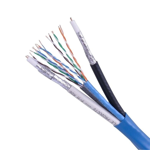
Indoor cable (PVC or LSZH jacket) is cheaper but unsuitable for wet or UV-exposed environments. Fiber optic cables are essential components in today's broadband, FTTx, and data center networks. Whether you're planning a national fiber rollout or sourcing cables for enterprise infrastructure, understanding how fiber optic cable pricing works can help you budget more effectively and make better. Buyers typically pay for fiber optic cable by length, fiber type, and installation complexity. Main cost drivers include cable grade (indoor vs outdoor, armoured), distance, and labor for trenching, splicing, and termination. This guide presents ranges in USD and practical price estimates to help. Optic cable price represents a crucial consideration in modern telecommunications infrastructure, reflecting the complex interplay of manufacturing costs, technological advancement, and market demand. These essential components of digital communication networks vary in price based on several key. * Disclaimer: Prices fluctuate based on raw material indices (Glass/Copper/Polymer) and cable core count (e. This feature makes them ideal for high-voltage power lines where both grounding and data transmission are needed. On the other hand, standard fiber optic cables 4 focus solely on data transmission and are.
[PDF]

In a metal box, a wire type equipment grounding conductor can be attached to the box with a ground screw or clip and terminated to the switch or receptacle in the box. Connecting the receptacle grounding terminal to the metal box ensures an effective ground-fault current path. The basic rule achieves this through an equipment grounding jumper; four exceptions. A main bonding jumper is required to bond the service disconnect enclosure to the service neutral conductor [250. Not all boxes are metal or provide. The main bonding jumper bonds the neutral conductor to the equipment grounding conductor, enabling proper operation of overcurrent protective devices. Neutral conductors must be properly sized based on the load and installation method, with specific requirements for conductors in parallel or. According to the National Electrical Code (NEC), this connection is made between the grounded conductor (typically the neutral) and the equipment grounding conductor (EGC) system at the service equipment. Proper location and sizing are not just best practices; they are essential for ensuring that. NEC Article 250 is dedicated entirely to grounding and bonding, outlining the specific conductors and connections required. Grounding Electrode Conductor (GEC): This is the wire that connects the grounding electrode (the rod) to the grounding bus bar in the main electrical panel.
[PDF]
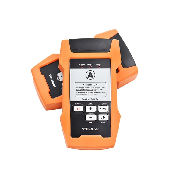
An electrical pigtail is a short piece of wire used to connect an electrical device, such as a switch or receptacle, to the main circuit conductors within a junction box. It acts as a jumper between the device terminal and the spliced bundle of circuit wires. This technique ensures the device is. Are a pigtail and a jumper wire the same thing, how are they different ? A jumper connects two devices or terminals together. Like you can jumper the top and bottom halves of a duplex receptacle if the bridge gets broken off. You can. The most intuitive difference between the two is that only one end of the pigtail has a connector, and both ends of the jumper have a connector. Optical Fiber Jumper: also known as optical fiber connector, both ends have connectors. Similar to coaxial cable, but without mesh shielding, for jumper. This detailed guide will take you through the basics of jumper wires, their types, applications, and the step-by-step process of connecting them securely and effectively. What Are Jumper Wires? Jumper wires are insulated wires used to connect two points in a circuit. They usually come with. Pigtails play a crucial role in ensuring safe and efficient connections within electrical systems, especially when dealing with multiple wires or limited space. Understanding what a pigtail is and how it works can make your wiring projects smoother and safer.
[PDF]
ODF, also known as optical distribution frame or fiber optic patch panel, is a critical device used in optical communication for managing and distributing optical fibers. It is usually a compact and structured framework composed of a steel shell and internal fiber splice tray as the. This complete guide explores everything you need to know about ODFs — from their structure, types, and key components, to installation best practices and modern design trends. Whether you're building a central office, data center, or FTTx distribution network, understanding the right ODF. An Optical Distribution Frame (ODF) is the central hub for fiber splicing, termination, patching, and cable protection in modern optical networks. Mainly used in the junction point between the optical transport networks and the optical transmission equipment, or bet een the optical fiber access networks and the user cable. It serves as a merging point for the optical fibers, where connections are consolidated and routed, thus minimizing signal attenuation. The ODF includes.
[PDF]