The optical module is usually composed of Transmitter Optical Subassembly (TOSA, containing a laser LD Chip), Receiver Optical Subassembly (ROSA, containing a photodetector PD Chip), a driving circuit, and an optical and electrical interface. Its schematic is shown in. This section explains the structure of a typical pigtail butterfly module, which gets its name from the two rows of seven leads at right angles on each side of the metal package plus an optical fiber pigtail at one end (Fig. Let's look at the internal structure (Fig. 2) of a common butterfly. Optical modules are devices used to connect network devices, transmit and receive data between network devices, and can be used to convert optical and electrical signals. The optical module is a very important component in an optical communication system. Optical devices are the core components of optical modules. TOSA and ROSA in Common Optical Transceiver Modules For ordinary optical transceiver modules, there are two optical devices, TOSA and ROSA, which have opposite effects.
[PDF]

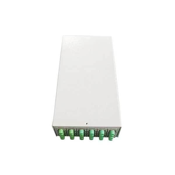
An Optical Splitter, also known as a beam splitter, is a passive optical device that divides a single input optical signal into two or more output signals. Conversely, it can also combine multiple signals into one. Knowing the difference between a splitter and an optical coupler helps you build better networks. You make your network work better when you pick the right device for each job. You can connect many users to one port with 1:n or 2:n splitters. By dividing a single optical signal from a central Optical Line Terminal (OLT) into multiple outputs for Optical Network Terminals (ONTs) at users' homes, splitters eliminate the need for dedicated fibers to each residence—slashing infrastructure costs while scaling network reach. This guide. In a Passive Optical Network (PON), a single optical fiber carries massive amounts of data using light. Signal Input: The fiber splitter receives the optical signal from the upstream network node and enters the splitter through the input fiber. Signal Distribution: Inside the splitter, according to the design structure and different. Splitters are passive optical devices that divide or combine optical signals, and they come in various types, including power splitters, uneven splitters, and wavelength-division multiplexing (WDM) splitters. Each type serves specific applications, enabling efficient use of optical infrastructure.
[PDF]

Cable Trays* — Max two 24 in. (610 mm) wide by max 6 in. (151 mm) deep open-ladder cable tray with channel-shaped side rails formed of 0. 54 mm) thick aluminum or min 0. In practice, cable tray dimensions are a system of interrelated measurements —width, depth, length, and material thickness—that directly affect cable fill compliance, heat dissipation, structural loading, and long-term expandability. From an engineering standpoint, cable tray dimensions are not. Perforated Cable Tray System expertly constructed from high-grade stainless steel, offering exceptional durability and resistance to corrosion. With side height 100mm. A properly designed and installed cable tray system will provide. Studs — Wall framing to consist of wood studs or channel shaped steel studs. Wood studs to consist of nom 2 by 4 in. Additional studs shall be used to completely frame. Best Size: Here, deep trays (75mm to 150mm) are used since power cables are typically thick and heavy. Data cables, such as your Wi-Fi or computer ones, are extremely sensitive. They do not get hot; however, they do not like to hang or sag. In case a data cable folds in an excessive manner, the. ect the minimum bend ra-dius for cables as they exit the bottom of the cable tray. A rung spacing of 6 to 9 inches (150 to 230 mm) is preferable when the cable tray cont d for instrumentation and control applications that require additional protec eferred to support and protect numerous small.
[PDF]

While traditional fiber optic cables contain individual fibers encased in a protective jacket, ribbon fiber cables organize fiber optic strands in a flat ribbon structure, creating freedom with space conservation and cable management. Data Centers: The flexible ribbon cables deliver phenomenal bandwidth between densely packed servers and networking gear in data centers. Motor Meter: Ribbon cables can be used to connect the control circuitry to the display or to the motor drivers. Telecom Devices: In telecommunications, flat. Ribbon cables offer higher fiber counts and greater fiber density than any other cable construction designed for the outside plant (OSP), four times the highest-fiber-count loose tube cable. Ribbon cables also enable mass-fusion splicing, whereby each 12-fiber ribbon can be spliced in a single. The technology of ribbon fiber optic cables is well-established in the telecommunications industry and is favored for its high fiber density and compact size. Join us as we embark on a journey of discovery, demystifying the technology that has changed the way we connect and communicate. Welcome to the world of Ribbon Fiber Optic Cables. One of our most innovative technologies is the ribbon fiber optic cable —a compact, powerful solution that is transforming the way organizations manage high-density connections while optimizing valuable space. In this article, we'll delve into why ribbon fiber optic cables are a game-changer, how.
[PDF]

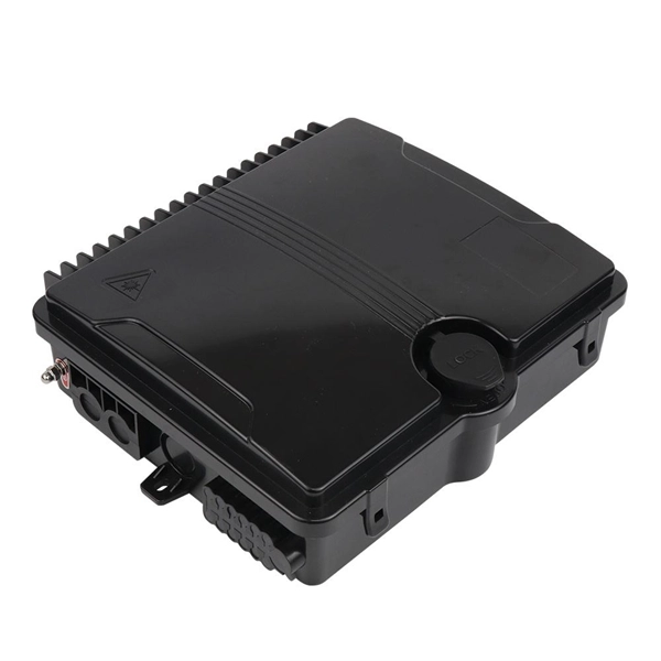
The main components of a splice box are the splice cassette that picks up the fibers and their reserves, and the front panel which contains different connectors for transmitting signals via copper or fiber optic cables. A splice box (also known as splice distributor) is a housing in which fiber optic cables begin or end. Fiber optics are fanned out in splice boxes that are situated at the end of fiber optic transmission paths. It typically consists of two parts: an outer housing and an internal structure. In this response, we will focus on the. The FSB series of indoor wall mount enclosures are designed for centralized splice-only applications. These boxes are well suited as optical cable splice collection points for DAS (Distributed Antenna Systems), MTU (Multi-Tenant Unit) commercial business applications, and MDU (Multi-Dwelling Unit). Fiber optic splice closures permanently connect two fiber optic cables together and have a splice that protects the components. The optical cable connection part, that is, the optical cable joint, is the part that protects the connection between two or more optical cables by the optical cable. Splicing refers to the permanent connection of two optical fibers to form a continuous optical connection.
[PDF]
This comprehensive guide breaks down the internal structure, core components (TOSA, ROSA, lasers), and operational mechanisms of SFP optical modules, enriched with technical insights and real-world applications. SFP (Small Form-factor Pluggable) optical modules are compact, hot-pluggable transceivers that enable network equipment to connect seamlessly to fiber and copper links. As a leading provider of optical communication solutions, Weunion integrates these. One vital element in the data communication sector is the Small Form-factor Pluggable (SFP) module. In this blog, we will explore the inner workings of these modules, with a particular focus on three essential optical components: TOSA, ROSA, and BOSA. SFP modules are small, hot-swappable devices. Optical modules are devices used to connect network devices, transmit and receive data between network devices, and can be used to convert optical and electrical signals. The optical module is a very important component in an optical communication system. Think of it as the “translator” for your network equipment, converting electrical signals into optical signals. available with a variety of types of copper SFP and fiber SFPs, SFP+. This transceiver module is compliant wi h the small form-factor pluggable (SFP) multi-source agreement (MSA). They industrial performance with an extended operating temperature range. Through real-time monitoring, the DDM.
[PDF]
There are several different physical mechanisms that can be used to amplify a light signal, which correspond to the major types of optical amplifiers. In doped fiber amplifiers and bulk lasers, stimulated emission in the amplifier's gain medium causes amplification of incoming light.OverviewAn optical amplifier is a device that amplifies an directly, without the need to first convert it to an electrical signal. An optical amplifier may be thought of as a without an, or one in which. The principle of optical amplification was invented by on November 13, 1957. He filed US Patent US80453959A on April 6, 1959, titled "Light Amplifiers Employing Collisions to Produce Population Inversions".
[PDF]

As illustrated in typical SFP internal structure diagrams, the module's core components include an optical transmitter assembly (TOSA), laser driver, optical receiver assembly (ROSA)—some high-sensitivity modules (like L16. 2) use APD receivers, which require an additional booster. The optical module serves as a crucial component in optical fiber communication systems, operating at the physical layer, which is the lowest layer in the OSI model. Its primary function is to achieve optoelectronic conversion by converting electrical signals into optical signals and vice versa. Among various optical module form factors, SFP (Small Form-Factor Pluggable). The function of the optical module is to carry out the photoelectric and electro-optic conversion. In this article, ETU-LINK will introduce to you what are the core components of the optical module? 1. TOSA: Its main function is to convert electrical signals to optical. the embodiments of the present applicationprovide an optical emission module, an emission device, a detection device and a terminal, which can improve the energy density of a light spot formed by an emission light beam and improve the integration of the device. an embodiment of the present.
[PDF]
A passive optical network (PON) is a fiber-optic telecommunications network that uses only unpowered devices to carry signals, as opposed to electronic equipment. In practice, PONs are typically used for the last mile between Internet service providers (ISP) and their customers. In this use, a PON has a point-to-multipoint topology in which an ISP uses a single device to serve many end-us. Components and characteristicsA passive optical network consists of an (OLT) at the service provider's central office (hub), passive (non-power-consuming) optical splitters, and a number of (ONUs) or. Passive optical networks were first proposed by in 1987. Two major standard groups, the (IEEE) and the. A PON takes advantage of (WDM), using one wavelength for downstream traffic and another for upstream traffic on a (ITU-T, typically OS2). BPON, EP.
[PDF]
Users often find key cabinets inside, such as incoming line, outgoing line, and capacitor compensation cabinets. Main internal parts include circuit breakers and protection devices. Low voltage distribution boxes manage and distribute electrical energy safely, ensuring easy. The internal structure of the distribution box is designed to safely distribute power from the main power source to multiple branch circuits. It provides convenience for protection, control and maintenance. This article discusses the construction of the distribution box, its functional divisions. A distribution box is a key part of electrical systems in buildings. It helps control and distribute electricity to different areas. Contact for purchase: WhatsApp +8615858778282. more This video details the design standards of this red construction. The three-level distribution system refers to a system that distributes electric power through three levels of distribution devices from the incoming power line at the construction site to the electrical equipment. This panel acts as the heart of an electrical network. It ensures that circuits are safe, organized, and easy to manage. This device supplies power to end-user devices and ensures safe, easy access at the point of use. The low voltage distribution box controls, protects, and.
[PDF]
Uses 12 wavelengths derived by shifting 6 traditional CWDM wavelengths left and right (±3. 5nm) using temperature tuning. Balances cost and channel density. Applications: Primarily 5G mobile fronthaul and midhaul networks requiring moderate capacity and cost efficiency. In fiber-optic communications, wavelength-division multiplexing (WDM) is a technology which multiplexes a number of optical carrier signals onto a single optical fiber by using different wavelengths (i., colors) of laser light. This technique enables bidirectional communications over a. This is the complete guide to Dense Wavelength-Division Multiplexing (DWDM) wavelengths and channels in 2024. Then, you will enjoy this new complete DWDM wavelength channels guide. What are the benefits of DWDM? #3. DWDM and CWDM enable carriers to deliver more services over their existing fiber infrastructure by combining multiple wavelengths on a single fiber. But navigating the alphabet soup of CWDM, DWDM, MWDM, LWDM, and SWDM can be daunting. 5 nm (800 GHz) in the O-band of 1270–1330 nm by using x-cut lithium-niobate-on-insulator (LNOI) photonic waveguides for the first time.
[PDF]
The QSFP+ module is designed for 40GBASE Ethernet throughput up to 10km over single-mode fiber (SMF) using a wavelength of 1310nm via duplex LC connectors. This transceiver complies with QSFP+ MSA and IEEE 802. 3ba 40GBASE-LR4 and OTU3 C4S1-2D1 standards. The Cisco 100GBASE Quad Small Form-Factor Pluggable (QSFP) portfolio offers customers a wide variety of high-density and low-power 100 Gigabit Ethernet connectivity options for data center, high-performance computing networks, enterprise core and distribution layers, and service provider. An Optical Transceiver is a critical optoelectronic component that facilitates seamless electro-optical (E-O) and photo-electric (O-E) conversion within fiber-optic networks. Cost-effective active optical components Rich experiences of producing and exporting ZION provides a range of high-quality, independently verified active optical components suitable for diverse settings, from large venues to small businesses. Their wide product selection caters to specific. Explore how AI clusters are reshaping network architecture, from XPU-centric design to multi-plane scalability, and learn how 800G modules enable high-performance, low-latency interconnects for modern AI data centers. In the design of AI computing clusters, Scale-Up and Scale-Out have different.
[PDF]
A KVM switch (with KVM being an abbreviation for "keyboard, video, and mouse") is a hardware device that allows a user to control multiple computers from one or more sets of keyboards, video monitors, and mouse. NameSwitches to connect multiple computers to one or more peripherals have had multiple names. The earliest name was. USB keyboards, mice, and I/O devices are the most common devices connected to a KVM switch. The classes of KVM switches discussed below are based on different types of core technologies, which vary in how the KV. A KVM Switch is a hardware device used in that allows the control of multiple computers from a single keyboard, monitor and mouse (KVM). The switch allows data center personnel to connect to any server.
[PDF]
Fiber optic cables use total internal reflection to keep light signals bouncing within the core, allowing data to travel quickly and with minimal loss. An optical fiber is comprised of a light-carrying core in the center, surrounded by a cladding that acts to traps light in the. Optical fibers are thin glass rods that use the properties of light reflection and refraction to transmit data over long distances. They actively shuttle data encoded in pulsing light across vast distances using only subtle differences in materials. They consist of three elements as shown in Figure 1: a central core, cladding and a protective coating. Optical fibers operate on the principle of total internal reflection, which. Refraction and total internal reflection (TIR) are the two fundamental optical principles that allow light to propagate through optical fibers over long distances with minimal loss. Understanding these mechanisms is essential for designing, installing, and troubleshooting fiber networks in FTTH. Fiber optic cables use a similar concept to guide light. Fiber optic. Describe the workings and uses of fiber optics. Analyze the reason for the sparkle of diamonds. A good-quality mirror may reflect more than 90% of the light that falls on it, absorbing the rest.
[PDF]

Figure 1 is a diagram of the basic construction of both loose-tube and tight-buffer fiber optic cable. An optical fiber cable is a complex structure designed to protect fragile glass fibers that transmit digital data using light signals. This advanced cabling solution allows fast, secure data transfer and telecom over long distances. Understanding the components within a fiber optic cable enables. A fiber optic cable consists of five basic components: the core, the cladding, the coating, the strengthening fibers, and the cable jacket. When searching for a fiber optic cable, we need to pay attention not only to the connectors, such as SC to ST fiber cable, LC to SC fiber patch cable, or SC to. Optical fibers are circular dielectric wave-guides used to contain and transmit light over short or long distances. They consist of three elements as shown in Figure 1: a central core, cladding and a protective coating. Understanding its internal structure is essential to appreciate how it functions efficiently in various applications, from telecommunications to medical devices. The core is the. 3,260 optical fiber structure illustrations, drawings, stickers and clip-art are available royalty-free for download. Multimode all-media self-supporting fiber optic cable structure isolated on white. More specifically, we can say that it is a waveguide that has the ability.
[PDF]