
Cable Trays* — Max two 24 in. (610 mm) wide by max 6 in. (151 mm) deep open-ladder cable tray with channel-shaped side rails formed of 0. 54 mm) thick aluminum or min 0. In practice, cable tray dimensions are a system of interrelated measurements —width, depth, length, and material thickness—that directly affect cable fill compliance, heat dissipation, structural loading, and long-term expandability. From an engineering standpoint, cable tray dimensions are not. Perforated Cable Tray System expertly constructed from high-grade stainless steel, offering exceptional durability and resistance to corrosion. With side height 100mm. A properly designed and installed cable tray system will provide. Studs — Wall framing to consist of wood studs or channel shaped steel studs. Wood studs to consist of nom 2 by 4 in. Additional studs shall be used to completely frame. Best Size: Here, deep trays (75mm to 150mm) are used since power cables are typically thick and heavy. Data cables, such as your Wi-Fi or computer ones, are extremely sensitive. They do not get hot; however, they do not like to hang or sag. In case a data cable folds in an excessive manner, the. ect the minimum bend ra-dius for cables as they exit the bottom of the cable tray. A rung spacing of 6 to 9 inches (150 to 230 mm) is preferable when the cable tray cont d for instrumentation and control applications that require additional protec eferred to support and protect numerous small.
[PDF]
will introduce major upgrades to its Multi-Rail technology platform at ECOC 2025, targeting hyperscale optical transport with new efficiency, scale, and performance enhancements. Coherent Corp. SAXONBURG, PA, September 26, 2025 (GLOBE NEWSWIRE) – Coherent Corp. At the heart of the. SAXONBURG, Pa. At the heart of the. Simultaneously, coherent technology has emerged as the prevailing solution for Data Center Interconnection (DCI) applications, covering distances of 80~120km in the field of data communication. These evolving applications introduce new demands for coherent optical transceiver systems, steering the. Coherent optical module refers to a typically hot-pluggable coherent optical transceiver that uses coherent modulation (BPSK / QPSK / QAM) rather than amplitude modulation (RZ/ NRZ / PAM4) and is typically used in high-bandwidth data communications applications. Optical modules typically have an.
[PDF]

Explore our comprehensive SFP optical module selection guide for 2025. Learn about crucial factors like data rate, distance, fiber type, and compatibility to optimize your network performance and cost-effectiveness. Make informed decisions for your networking needs today!. SFP (Small Form-factor Pluggable) is a compact, hot-pluggable network interface module used to connect network devices (switches, routers, firewalls) to fiber optic or copper cables. They're essential for extending network distances and increasing bandwidth capabilities. Selecting the correct SFP module is not simply a matter of matching connectors. In modern Ethernet networks, choosing the wrong transceiver can result in link failures, speed mismatches, compatibility errors, or unexpected distance limitations. For network engineers, system integrators, and IT. At the core of these advanced networks are bidirectional SFP modules, also known as BiDi SFP transceivers—compact, cost-efficient devices that support high-speed data transmission and reception over a single optical fiber. By using different interfaces and single-mode or multimode fiber depending on the.
[PDF]

This guide explains how to make 90° bends, vertical bends, tees, and offsets in wire mesh cable trays safely and professionally. Horizontal 90° Bend (Flat Bend) 2. Tee (T-Junction) Bend 4. Since the jaws of the bolt cutter drags a layer of zinc across the cut end and forms a protective layer. When a wire cable tray is cut, the fact that a. Wire mesh cable trays are widely used because of their flexibility and easy on-site modification. Unlike perforated trays, bends can be created directly at site without expensive fittings. Great if you are new or just forgot how to do it, this easy to follow guide makes it so simple. more The Easy Guide to. This involves a few essential steps to ensure a successful bending process. The first step in preparing the. The method for producing bridge bend elbows is as follows: Take a 90-degree cable tray bend elbow as an example, and apply the same principles for 45-degree bends accordingly. The length of the bottom side (bottom diagonal) after bending the cable tray should be equal to the width of the cable. OTHER THAN 90 ̊ JUNCTIONS Use this guide to learn the most effective installation practices when installing Cablofil tray. Each example of bends and tee's clearly illustrate proper tray cutting combined with recommended usage of Cablofil accessories. Engineers and contractors in North America and.
[PDF]

The formula for calculating electrical box size is: . The formula for calculating electrical box size is: . Free electrical load calculation tool for residential and commercial buildings. Calculate service entrance sizing, panel loads, demand factors, and ensure NEC Article 220 compliance. Important: Load calculations must comply with NEC Article 220 and local codes. Always verify calculations with a. How to choose a distribution box of the right size for a project based on load current? If you're like most electrical professionals, picking the right distribution box for your project can feel like navigating a maze. I've been in those shoes - staring at spec sheets, worrying about. The National Electrical Code (NEC) specifies minimum box sizes based on wire gauge and quantity. Proper sizing ensures safety, ease of maintenance, and compliance with regulations. This calculator helps you determine the minimum required box volume based on the number of wires, devices, ground wires, and clamps involved. This ensures compliance with electrical codes and prevents overcrowding. Choose a standard or custom box volume watch capacity update with clear pass or fail status plus tips examples CSV and PDF export for documentation Works for common sizes supports.
[PDF]

An Optical Splitter, also known as a beam splitter, is a passive optical device that divides a single input optical signal into two or more output signals. Conversely, it can also combine multiple signals into one. Knowing the difference between a splitter and an optical coupler helps you build better networks. You make your network work better when you pick the right device for each job. You can connect many users to one port with 1:n or 2:n splitters. By dividing a single optical signal from a central Optical Line Terminal (OLT) into multiple outputs for Optical Network Terminals (ONTs) at users' homes, splitters eliminate the need for dedicated fibers to each residence—slashing infrastructure costs while scaling network reach. This guide. In a Passive Optical Network (PON), a single optical fiber carries massive amounts of data using light. Signal Input: The fiber splitter receives the optical signal from the upstream network node and enters the splitter through the input fiber. Signal Distribution: Inside the splitter, according to the design structure and different. Splitters are passive optical devices that divide or combine optical signals, and they come in various types, including power splitters, uneven splitters, and wavelength-division multiplexing (WDM) splitters. Each type serves specific applications, enabling efficient use of optical infrastructure.
[PDF]
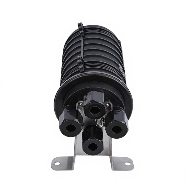
This fiber splicing dome enclosure comes with six splice trays that accommodate up to 96 unterminated cables to give you more flexibility in adjusting cable lengths and connection types directly on-site. The optical fiber splicing tray is designed to provide a location for storing and protecting optical cables and splicing. It is mainly used for management of cable junction box and wall mounted junction box. They are equipped with splice holders, compatible with all standard types of heat shrink or crimp type splice protectors, and provide enough space for storage and management of the excess fiber. PPC ofers a. Corning has a wide variety of hardware solutions to choose from to fit your cabling needs. Choose from racks, panels, modules, splice trays, ethernet fiber switches and other structured cabling components. Corning has a variety of hardware solutions including ethernet fiber switches, panels, racks. $ {cardName} unavailable for quantities greater than $ {maxQuantity}. Brief content visible, double tap to read full content. Would you like to tell us about a lower price? Found a lower price? Let us know. Although we can't match every price. Discover CommScope fiber splice trays, fiber optic splice trays, and a convenient fiber splice organizer. Each tray provides space for mounting fiber splice protectors and excess fiber. Optical fiber glass.
[PDF]

The video tutorial demonstrates the depin and repin method for repairing automotive wiring harness connectors, specifically pigtails. It outlines seven easy steps to replace a pigtail connector, making it accessible for DIY enthusiasts and individuals dealing with electrical issues. This comprehensive guide will equip you with the knowledge and skills to accurately assess the integrity of a pigtail, helping you identify issues before they escalate into larger problems. We'll explore different testing methods, delve into the interpretation of multimeter readings, and offer. The latest in the line of Ford Flex Probe Kits, this newest release includes all the probes from the previous “D” kit, but now adds two each of the Micro Pin (. Additionally, all probes will now be printed with the tip size, helping technicians ensure usage of the properly sized tip. Short answer: An automotive wiring pigtail is a short section of wire with a pre-attached connector that lets you repair or replace a damaged plug without replacing the entire harness. It provides a plug-and-play repair solution that restores OEM fit, seal, and electrical reliability. Key steps. At FindPigtails. com, we specialize in high-quality, OEM connector replacement. Why pay thousands for a complete wire harness, when you can simply replace the damaged connector? We invite you to take a look at some of our instructional videos, for step-by-step guides of de-pin and re-pin procedures.
[PDF]
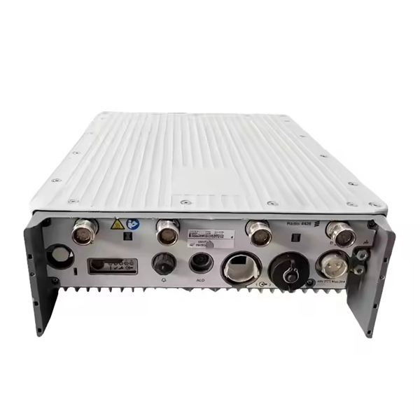
Usually, the 10G/25G grey light optical modules with a short transmission distance are applied for connecting AAU/DU with WDM/OTN/SPN. The connections between WDM/OTN/SPN network devices can be achieved by 10G/25G/50G/100G dual-fiber or single-fiber bidirectional. Compared with Draft A (2013-07-30), this issue includes the following new topic: 2. This section describes engineering specifications of an AAU, including input power and equipment specifications. 7. In 2/3/4G networks, 10Gbps optical modules are generally enough for CPRI interfaces. In 5G networks, CPRI is also upgraded to eCPRI. Currently, 5G of the bearer network mainly uses 25Gbps optical modules. Next, ETU-LINK will introduce the types of optical modules used by 10G SFP+ and 25G SFP28. What is the difference between the 5G bearer network and the traditional optical transmission network? The main difference is that 5G fronthaul needs to support CPRI/eCPRI protocol. Most of the AAU of 5G base stations are deployed outdoors. In order to resist harsh environments such as high. The optical modules used to connect BBU and RRU devices are optical modules and optical fibers. Product Versions The following table lists the product versions related to this document. 25G SFP optical module adopts the wavelength of 850nm, with an operating.
[PDF]
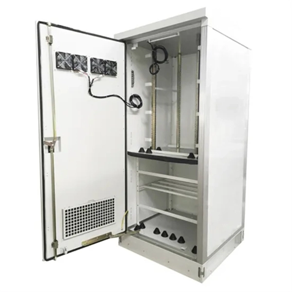
See a sample diagram and download it in different formats. Electrical enclosure sizes are not universal, but most manufacturers follow common size families. This guide explains typical wall-mount and floor-standing dimensions, how to read catalog sizes, and how to choose the right enclosure size for your layout. What Are Electrical Box Dimensions? Electrical box dimensions typically refer to: Correct dimensions ensure:. Solid rubber (construction) distribution box suitable for construction and industry according to EN-61439-4. Available from stock. The only one in the Benelux with a Dekra quality mark. Distribution boxes 32 Amp. Explorez notre Guide Complet du RGIE : Schémas Électriques, Conseils de Conformité, Assistance Gratuite pour la Sécurité et la Mise aux Normes des Installations, et Accès Direct aux Électriciens et Agences Agréées. Discover easy access to the Belgian Electrical Regulations resources, structured. Sheet Electrical: Electricity symbols for floor plans (based on Belgium regulations). Learn more about these objects, how they can be added to your Dia toolbox and how you can draw your diagrams with them. Boxes distribute low currents in an area equipped with 1 to 12 RJ 45 sockets. They centralise connections to ensure flexibility and that the installation is up to date. Area boxes can be installed in technical flooring or in false ceilings.
[PDF]
