A typical fiber optic splice enclosure consists of several key components that work together to protect and organize the fiber splices. Standard enclosures contain: 1) Housing, 2) Cable fixation clamps, 3) Splice trays, 4) Sealing system. A splice box (also known as splice distributor) is a housing in which fiber optic cables begin or end. Fiber optics are fanned out in splice boxes that are situated at the end of fiber optic transmission paths. Optical cable joint box The optical cable joint box permanently connects two optical cables together and has a joint part for protecting components. The optical cable connection part, that is, the optical cable joint, is the part where the. An optical cable split fiber box, also known as a fiber distribution box or fiber optic splice closure, is a device used to terminate, splice, and distribute optical fibers. In this response, we will focus on the. This guide optimizes the original text by delving deeper into the three pillars of fiber network longevity: the impact of splicing technology, the strategic selection of splice boxes, and the essential maintenance protocols needed to ensure sustained, high-speed functionality. Fibre optic cables are manufactured in standardized lengths –.
[PDF]
In fiber optic circuit technology an optical fiber link is used for transferring digital or analogue data in the form light frequency through a cable which has a highly reflective central core. Internally, the optical fiber.
[PDF]

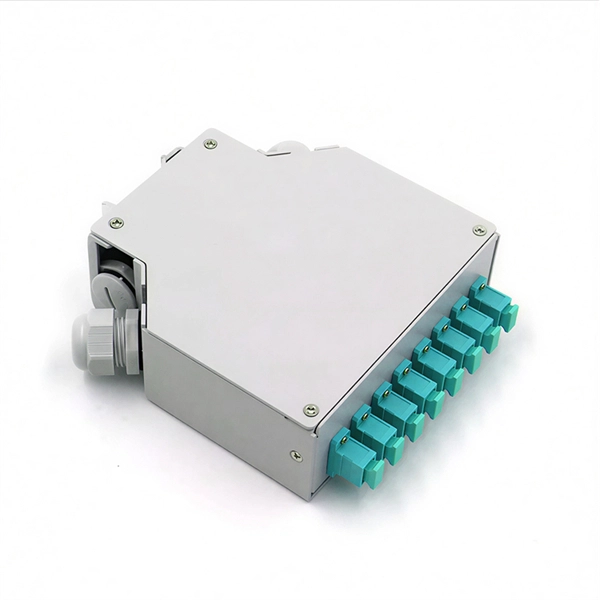
The main components of a splice box are the splice cassette that picks up the fibers and their reserves, and the front panel which contains different connectors for transmitting signals via copper or fiber optic cables. A splice box (also known as splice distributor) is a housing in which fiber optic cables begin or end. Fiber optics are fanned out in splice boxes that are situated at the end of fiber optic transmission paths. It typically consists of two parts: an outer housing and an internal structure. In this response, we will focus on the. The FSB series of indoor wall mount enclosures are designed for centralized splice-only applications. These boxes are well suited as optical cable splice collection points for DAS (Distributed Antenna Systems), MTU (Multi-Tenant Unit) commercial business applications, and MDU (Multi-Dwelling Unit). Fiber optic splice closures permanently connect two fiber optic cables together and have a splice that protects the components. The optical cable connection part, that is, the optical cable joint, is the part that protects the connection between two or more optical cables by the optical cable. Splicing refers to the permanent connection of two optical fibers to form a continuous optical connection.
[PDF]

Optical fiber technology has revolutionized the way we communicate, enabling fast and reliable data transmission over long distances. In this article, we will explore the different types of optical fibers used in communication systems and their applications. Fiber Optics or Optical Fiber is a technology that transmits data as a light pulse along a glass or plastic fiber. An Optical Fiber is a cylindrical fiber of glass that is hair-thin in size or any transparent dielectric medium. The fiber which is used for optical communication is waveguides made of. Optical fibers are the backbone of modern communication. They transmit light signals over long distances with minimal loss. Let's break down their classification in a simple and engaging way: 1. The less signal damage metal wires can cause, the better for optical fiber connection. Total internal reflection (critical angle, using Snell's law). Higher bandwidth (extremely high data transfer rate). Less signal degradation. Less costly per meter. Lighter and thinner then copper wire. The light is a form of carrier wave that is modulated to carry information. The cladding's refractive index is slightly smaller than that of the core, which confines light within the core and propagates by repeated total reflection at the boundary with the.
[PDF]

Typical rates range from $0. 00 per ft depending on terrain, access, and required precision for termination. Basic — 1,000 ft single-mode run indoors with minimal termination: Cable $0. 00/ft, Permits $150, Accessories $100. Total ≈ $2,650–$3,100. Fiber-optic cable materials typically cost $1 to $6 per linear foot, depending on fiber count and cable type. Commercial building installations with 100-200 network drops generally range from $15,000 to $30,000. Single-mode fiber costs less per foot than multimode fiber, but it requires more. Buyers typically pay for fiber optic cable by length, fiber type, and installation complexity. Main cost drivers include cable grade (indoor vs outdoor, armoured), distance, and labor for trenching, splicing, and termination. This guide presents ranges in USD and practical price estimates to help. The cost per foot of fiber optic cable is now the lowest it's been since 2021. Labor dominates the installed price. Here is the 2026 benchmark for cost of laying fiber optic cable per foot by method: Open trench (lawn/field): $0. 80 per ft – fastest, lowest cost. Directional boring (road. Single-mode fiber (OS2): This is the industry workhorse. In 2025, the base glass price has stabilized. You are looking at $0. The price swing usually depends on the fiber count (e., 12-core vs 96-core) and brand. This article breaks down the price landscape and provides.
[PDF]
The Semiconductor Optical Amplifier (SOA) plays a vital role in boosting data transmission for long-distance fiber optic networks. Unlike traditional electronic amplifiers, SOAs amplify optical signals directly without converting them to electrical form. This article focuses on Semiconductor Optical Amplifiers (SOAs), Thulium-Doped Fiber Amplifiers (TDFAs), Praseodymium-Doped Fiber Amplifiers (PDFAs), and Hybrid Amplifiers. This method maintains data integrity over. Explore the functioning, types, advantages, and limitations of Semiconductor Optical Amplifiers (SOA) in modern optical communications. Primarily seen in telecommunication systems as Fiber-Pigtailed components, these components operate at signals. A key player in this arena is the Semiconductor Optical Amplifier (SOA).
[PDF]
Glass fiber and plastic fiber is fragile. When individual fibers break, light transmission and uniformity are reduced. After the first few fibers break at a stress point, a chain reaction occurs, hastening t.
[PDF]
Mid-Range — 2,000 ft outdoor run with conduit and 4 terminations: Cable $0. 60/ft, Permits $350, Delivery $120, Accessories $250. Total ≈ $4,940–$6,120. Multi-fiber cables worked as described and with no issues. Buy 4 Fibers OM3 Multimode PVC (OFNR) Indoor Tight Buffered Multifiber Pre-Terminated Cable at reliable fiber optic cable supplier, best price & Fast shipping. Typical rates range from $0. 00 per ft depending on terrain, access, and required precision for termination. Commercial building installations with 100-200 network drops generally range from $15,000 to $30,000. Single-mode fiber costs less per foot than multimode fiber, but it requires more. Aluminum Folding Telescopic Ladder 4. 4m for Home & Outdoor ₹ 6,550. 00 Original price was: ₹6,550. 4 Core FTTH Single Mode Optical Fiber Cable – Round OD 5. High quality fiber optic cables from Corning, AFL, OCC, Mohawk and other leading manufacturers. Aerial, ADSS, armored, distribution, direct burial and more. Pricing (USD) Filter the results in the table by unit price based on your quantity. A tariff of 8% may be applied if shipping to the United States.
[PDF]

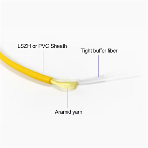
Contrary to popular belief, fiber optic cables do not contain copper. Instead, they consist primarily of glass or plastic fibers that transmit data using light signals. These fibers are surrounded by protective coatings made of materials such as polymer or epoxy resin. Fiber optic cables are designed to provide high-speed, no-signal-loss, and EMI-free communication in telecommunication, powergrid, datacenter, broadband, and industrial applications. Each optical cable is constructed using a precise combination of optical fibers, strength members, buffer tubes. Fiber optic cables use pulses of light through ultra-pure glass or plastic fibers to carry information rather than electrical signals. Cladding: Lower refractive index layer reflecting light back into. You might wonder if there's copper inside fiber optic cables. It's not a yes-or-no answer. So, it's about knowing the different types. Its primary method of data transmission relies on light signals traveling through glass or plastic fibers, rendering copper conductors unnecessary for that purpose. Fiber optic cables have revolutionized data transmission. The two core material technologies used in almost all cables are fiber optic, and copper wiring.
[PDF]

Arduino-Powered Data Transmission with Fiber Optics Welcome to our video tutorial on optical communication with Arduino, designed to be easy t. more. They consist of a transmitter on one end of a fiber and a receiver on the other end. Most systems use a "transceiver" which includes both transmission and. I'm going to use HFBR 1414 fiber optic transmitter module which is manufactured by Broadcom. It is a low-cost high-power transmitter that is designed for use in industrial power generation, power distribution, medical transportation and gaming applications. Internally, the optical fiber consists of a highly reflective central core, which acts like a light guide. Media converters are special fiber optic transceivers used to convert from one type of cable (the media) to another, typically from copper cables to fiber optics, although some media converters will convert from one fiber type to another, e. multimode to singlemode. The FOA Guide has a page about. A fiber optic transceiver (also called an optical transceiver) is a compact module that both transmits and receives data signals through optical fibers. It serves a dual purpose — transmitting electrical signals as light pulses and receiving light pulses to convert them back into electrical form.
[PDF]
Fiber testing is the process of verifying the performance of optical fiber cabling. This process includes a range of tests and measurements such as insertion loss, optical return loss, and fiber length. It encompass.
[PDF]
Fusion splicing is most widely used as it provides for the lowest loss and least reflectance, as well as providing the most reliable joint. Virtually all singlemode splices are fusion. 📦 For purchasing, use the RP Photonics Buyer's Guide for fiber cleavers. It provides an expert-curated supplier directory, buyer-focused technical background information, and structured selection criteria to support professional procurement decisions. In many applications of fiber optics, it is. The fiber optic quick connector/cold connector is a very innovative field-terminated connector, which contains factory-installed optical fiber, pre-polished ceramic ferrule and a mechanical splicing mechanism. The incoming optical fiber or indoor optical fiber can be inserted into the mechanical. A reliable fiber-optic network depends on more than selecting the right cable and connectors; it hinges on the quality of every splice. In fact the splice shall ensure high quality and stability of performance with time. Either joining method must have three primary characteristics. Fiber joints are the points where two optical fibers are permanently connected to create an uninterrupted transmission path. These connections are essential in fiber optic networks, enabling the extension, branching, or repair of fiber cables while ensuring minimal signal loss during transmission.
[PDF]

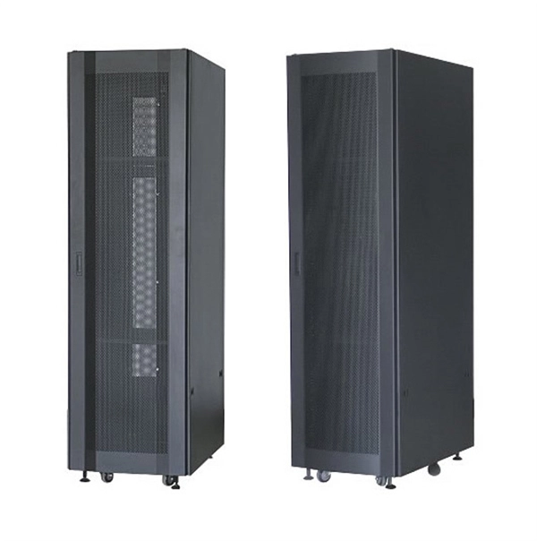
Here's a step-by-step guide to help you set up your fiber distribution box seamlessly: Before installing the fiber distribution box, ensure that your optical cables are properly prepared for connection. The optical fiber distribution box allows people to easily access the optical fibers in the box, and can well protect the optical fibers. In addition, the drawer structure also facilitates high-density wiring and good cable management. However, because optical fibers are fragile and can be easily. Keeping this page as a placeholder for now. Have any questions? Talk with us directly using LiveChat. Fix the rack to the ground with expansion bolts. Top installation: Dimensions of four connection holes on the top according to the. This instruction describes the installation of the Fiber Distribution Frame (FDF) manufactured by Corning Optical Communications. To order accessories that are purchased separately, contact Corning Optical Communications customer care for assistance. Read and understand this procedure (as well as. Optical fiber distribution frame is the wiring connection equipment between optical cable and optical communication equipment or between optical communication equipment. Distribution boxes are especially essential for FTTH networks, where they enable the efficient connection and management of optical fibers from a central.
[PDF]
The communication system of fiber optics is well understood by studying the parts and sections of it. The major elements of an optical fiber communication system are shown in the following figure. The ba.
[PDF]
Glass fiber and plastic fiber is fragile. When individual fibers break, light transmission and uniformity are reduced. After the first few fibers break at a stress point, a chain reaction occurs, hastening t.
[PDF]