
Cable Trays* — Max two 24 in. (610 mm) wide by max 6 in. (151 mm) deep open-ladder cable tray with channel-shaped side rails formed of 0. 54 mm) thick aluminum or min 0. In practice, cable tray dimensions are a system of interrelated measurements —width, depth, length, and material thickness—that directly affect cable fill compliance, heat dissipation, structural loading, and long-term expandability. From an engineering standpoint, cable tray dimensions are not. Perforated Cable Tray System expertly constructed from high-grade stainless steel, offering exceptional durability and resistance to corrosion. With side height 100mm. A properly designed and installed cable tray system will provide. Studs — Wall framing to consist of wood studs or channel shaped steel studs. Wood studs to consist of nom 2 by 4 in. Additional studs shall be used to completely frame. Best Size: Here, deep trays (75mm to 150mm) are used since power cables are typically thick and heavy. Data cables, such as your Wi-Fi or computer ones, are extremely sensitive. They do not get hot; however, they do not like to hang or sag. In case a data cable folds in an excessive manner, the. ect the minimum bend ra-dius for cables as they exit the bottom of the cable tray. A rung spacing of 6 to 9 inches (150 to 230 mm) is preferable when the cable tray cont d for instrumentation and control applications that require additional protec eferred to support and protect numerous small.
[PDF]
In general, foreign suppliers enter the Chilean market by appointing an agent, distributor, or wholesaler. Most are small-to-medium size firms. Several large firms handle different product lines and operate a.
[PDF]

Continuous-wave operation (cw operation): The laser is continuously pumped and emits light continuously, either on a single resonator mode (→ single-frequency operation) or on multiple modes (see also: single-mode operation). How do optical. EML stands for Externally Modulated Laser (corrected from "External Modulated Laser"). Its basic principle is to supply a constant current to the laser diode, ensuring the LD emits continuous, stable light. An external electro-absorption modulator (EAM) then adjusts light transmittance to generate. A wavelength swept light source emits laser light with a continuously sweeping wavelength. It is suitable for shape measurement and displacement measurement utilizing OFDR (Optical Frequency Domain Reflectometry), an optical sensing method using the coherence of laser light. The transmitting interface inputs electrical signals of a certain bit rate, which are then processed by internal driver chips. Subsequently, the driver semiconductor laser. Industry pundits have recently speculated that demand for 100G/400G switches may take off in 2019, prompting optical transceiver module vendors to sample data center switches with high data transmission rates earlier than expected. As data center operators accelerate upgrades in preparation for 5G.
[PDF]
At Multilink, we offer traffic power solutions to keep traffic signals, camera equipment, illuminated street signs and other tech up and running. Power traffic signals, camera equipment, lighting and other t.
[PDF]
If you encounter any of these issues, check the optical connector for damage or dirt, inspect the fiber optic patch cord, ensure the optical module is correctly installed, and check the device settings for compatibility. Subsequently, the driver semiconductor laser (LD) or light-emitting diode (LED) emits modulated optical signals at the corresponding rate. After transmission through the optical fiber, the receiving interface converts the optical signals into electrical signals using a photodetector diode and. An optical module is a typically hot-pluggable optical transceiver used in high-bandwidth data communications applications. Optical modules typically have an electrical interface on the side that connects to the inside of the system and an optical interface on the side that connects to the outside. The Transmitter Optical Sub Assembly (TOSA) is responsible for the emission of light. Its primary function entails converting electrical signals into optical signals.
[PDF]
This guide provides a fully updated and industry-ready overview of LC fiber optics, explaining the origin and design of LC connectors, their key features, and the complete ecosystem of LC-based products used in modern networking. It covers LC connectors, LC patch cables, uniboot designs, armored. LC stands for Lucent Connector (also colloquially “Little Connector”). It was introduced by Lucent Technologies to deliver small form factor (SFF) optical connections that match the density of RJ-45 copper ports. 25 mm ferrule (half the size of SC's 2. 5 mm) enables twice the port. Fiber optic connectors are used to the mechanical and optical means for cross connecting fibers. Fiber optic connectors can also be used to join fiber cables to transmitters or receivers. As a small-form-factor (SFF) interface, LC has become the default duplex connector in enterprise LANs, telco closets, and data-center topologies because it balances density, repeatability, and cost. SC connectors were originally designed for FTTH, but they were gradually popularized and used on a large scale due to their small size and convenience. You may find LC connector has a strong family which includes but not limited to LC optical fiber connectors, LC fiber patch cables, LC fiber.
[PDF]
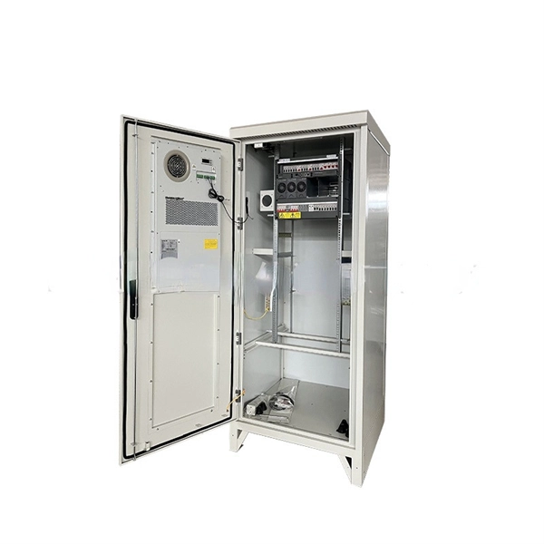
These products are highly integrated, compact in size, structurally compact, safe and reliable in operation, easy to maintain, and portable. In distribution systems, they can be used in ring network distribution systems as well as in dual power supply or radial terminal distribution. High voltage and low voltage complete sets occupy a significant place in modern electrical engineering as they are responsible for safe, secure, and efficient power distribution to all types of industries. They are known as complete switchgear assemblies because they integrate inside them such. Electricity plays a critical role in ensuring national well-being and livelihoods, and the stable development of the power industry drives socio-economic progress. To achieve structural adjustment and transformation in the power industry, the foremost priority is enhancing the performance of. Our high and low voltage complete electrical equipment solutions are designed based on a deep understanding of the current development trends in the power industry and accurate predictions of future power demand. It is mainly used to protect, control and isolate electrical equipment. Its primary functions are to cut off the power supply of equipment to facilitate subsequent maintenance. Senior Electrical Engineer, with 12 years of experience in high and low voltage switchgear installation, commissioning, and overseas project technical support. Currently, Thor is the Technical Department Manager at Weisho Electric Co.
[PDF]

The core measurement procedure follows five steps: Turn on the meter and let it warm up. Most meters need a brief stabilization period before readings are reliable. Check your model's manual, but a minute or two is typical. Set the wavelength to match your light source. Fiber loss is the difference between the power when light is coupled from the transmitting end to the fiber and the power when the light reaches the receiving end. Generally speaking, when measuring the. An optical power meter measures the strength of light traveling through a fiber optic cable, giving you a reading in dBm (decibels relative to one milliwatt). The basic process is straightforward: turn the meter on, set it to the correct wavelength, clean your connectors, plug in, and read the. A power meter and light source are essential test tools that work in tandem to measure fiber optic cable loss and evaluate the quality of optical links. They provide the data necessary to quantify signal loss and pinpoint issues that could impact network performance. Here's how they work: A power. You measure optical power in dBm or insertion loss in dB. Verify light travels from transmitter to receiver. We'll give you the basic information you need and provide some printable references.
[PDF]

Beamsplitters are capable of dividing the incoming light into several streams. A number of factors impacts this splitting process; for example, the wavelength, intensity, or polarity, or the incoming light; or the construction and settings of the beamsplitter itself. 📦 For purchasing, use the RP Photonics Buyer's Guide for beam splitters. It provides an expert-curated supplier directory, buyer-focused technical background information, and structured selection criteria to support professional procurement decisions. What are Beam Splitters? A beam splitter (or. A beam splitter or beamsplitter is an optical device that splits a beam of light into a transmitted and a reflected beam. It is a crucial part of many optical experimental and measurement systems, such as interferometers, also finding widespread application in fibre optic telecommunications. The first surface is coated with an all-dielectric film having partial reflection properties over either the visible or the near-infrared spectrum. Beamsplitters are often classified according to their construction: cube or plate. Beam splitters are a fundamental element in optical systems. This division allows for the simultaneous analysis or utilization of the light's properties along two separate paths. The device is purely.
[PDF]
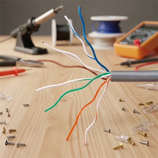
This is the first and crucial connection—attach the incoming live wire (typically marked with brown or red insulation) to the main terminal in the distribution box. Before you begin installing a distribution box, make sure you have the right tools and materials. Below is a quick checklist of everything you will need for a safe and efficient installation: Connecting a distribution box involves several steps to ensure proper electrical flow. Follow this guide. Applications - The minimally invasive retrofit kit enables the opportunity existing remote power infrastructure cross arm, & wiring) providing the total cost of ownership. Failure to strictly adhere to the warnings and cautions as well as the installation instructions may result in serious personal. Hey, in this article we are going to see the Single Phase Distribution Box Wiring Diagram and Connection Procedure. Whether you're an electrician or a DIY enthusiast, this guide will help you understand the basics of home electrical distribution. What is Distribution Board? Distribution board. Power source through switch box - When power comes through a box containing a light switch and continues on to the light, the switch is attached on one terminal to the black (or sometimes red) line from the power source and on the other terminal to the black (or red) line going on to the light.
[PDF]

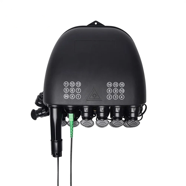
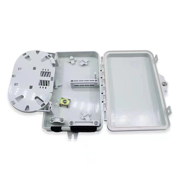
An Optical Splitter, also known as a beam splitter, is a passive optical device that divides a single input optical signal into two or more output signals. Conversely, it can also combine multiple signals into one. Knowing the difference between a splitter and an optical coupler helps you build better networks. You make your network work better when you pick the right device for each job. You can connect many users to one port with 1:n or 2:n splitters. By dividing a single optical signal from a central Optical Line Terminal (OLT) into multiple outputs for Optical Network Terminals (ONTs) at users' homes, splitters eliminate the need for dedicated fibers to each residence—slashing infrastructure costs while scaling network reach. This guide. In a Passive Optical Network (PON), a single optical fiber carries massive amounts of data using light. Signal Input: The fiber splitter receives the optical signal from the upstream network node and enters the splitter through the input fiber. Signal Distribution: Inside the splitter, according to the design structure and different. Splitters are passive optical devices that divide or combine optical signals, and they come in various types, including power splitters, uneven splitters, and wavelength-division multiplexing (WDM) splitters. Each type serves specific applications, enabling efficient use of optical infrastructure.
[PDF]

Its red laser shines through most yellow-jacketed optical fibers to help you pinpoint breaks, bends, faulty connectors, splices and other causes of signal loss. It has a reach of up to 5 km. The RPEN-210 is a necessity tool that should not be missing from any fiber plant manager or fiber optic installing technician. The Visual Fault Locator (VFL) Pen has a visible red light source centered on 650nm. Tool sends visible light over a fiber strand with a 10mW power, good enough to reach. The FLS-140 is the easiest way to identify optical fibers from end to end and locate polished connector endfaces. 5 dBm, but it couples approximately 3 dB less into a fiber. This is a Class 1 unit; the Class 1 limit is +3 dBm. The Class 1 limit (+3 dBm/2 mW) is intrinsically safe in all circumstances and is. This VFL has a fiber stub; its total emission is -1. 30 years of experience in R&D and manufacturing - Jilong JILONG launched the VFL-22M mini red light pen, pocket design, small and portable, integrated VFL/LED function, strong and stable light source, strong penetrating. A visible laser radiation source is one of the simplest devices and is designed to produce red light with a wavelength of 650 nm, which is transmitted through an optical fiber. The main purpose of this device is to locally detect various types of damage (such as breaks, bends, poor splicing, etc.
[PDF]

A beamsplitter is a common optical component that partially transmits and partially reflects an incident light beam, usually in unequal proportions. In addition to the task of dividing light, beamsplitters can be employed to recombine two separate light beams or images into a single. Beamsplitters are fundamental components in optical engineering, serving to precisely divide a single input beam of light into two distinct output beams. This division allows for the simultaneous analysis or utilization of the light's properties along two separate paths. It is a crucial part of many optical experimental and measurement systems, such as interferometers, also finding widespread application in fibre optic telecommunications. a laser beam) into two (or sometimes more) beams, which may or may not have the same optical power (radiant flux). Different types of beam splitters exist, as described in the. The beam splitter splits and then recombines infrared radiation, while the detector picks up the resulting signal. It's sensitive to both intensity and frequency. Together, they decide just how accurately an instrument captures those unique infrared “fingerprints” from different substances.
[PDF]
Visible light communication (VLC) is an advanced, highly developed optical wireless communication (OWC) technology that can simultaneously provide lighting and high-speed wireless data transmission. A VLC system has several key advantages: ultra-high data rate, secure communication channels, and a. In some situations, visible light communication (VLC) has considerable advantages over the more generally utilized radio frequency (RF). This chapter delves into the fundamentals of VLC, beginning with an insightful exploration of its background and subsequently addressing the advantages and. Efficiency, durability and long life span of LEDs make them a promising residential lighting equipment as well as an alternative cheap and fast data transfer equipment. Appliance of visual light in data communication by means of LEDs has been densely searched in academia. In this paper, we explore. Visual light source of Lano Technology is designed to meet the demands of various industries, our visual light sources deliver exceptional brightness and clarity, ensuring optimal visibility for your applications. With a wide range of product models available, you can find the perfect solution for. Below find pdf documentation available for Visual Lighting. You can also view the Visual Lighting Manual in web help format. Visual is powerful lighting software engineered to bring.
[PDF]

This guide will walk you through the process of checking photo sensors using a multimeter, covering various types of photo sensors, the necessary tools and safety precautions, and the specific measurement techniques involved. Knowing how to effectively use a multimeter to test photo sensors can save you time, money, and frustration when dealing with malfunctioning devices. more What is a Voltage Divider? | What is a Voltage. Before replacing the sensor or fixture, it's efficient testing it first, With a few tools and a step-by-step process you can find whether your outdoor lighting control system is working as intended or if the problem lies elsewhere. In this complete guide from Lead-Top, a global leader in photocell. In this blog post, we explain step-by-step how to troubleshoot a sensor with a digital multimeter (DMM). Here are the steps: Troubleshooting a sensor measurement failure requires mechanical tools to uncover the protective shields or components so you can reach the sensor in question. Always follow the manufacturer's instructions for the sensor and multimeter. Ensure the sensor is properly connected to the multimeter and. A multimeter is an indispensable diagnostic tool for anyone working with electronics, electrical systems, or indeed, sensors. It's a versatile device capable of measuring voltage, current, and resistance, providing crucial insights into the health and functionality of electrical circuits and.
[PDF]


