Pricing (USD) Filter the results in the table by unit price based on your quantity. A tariff of 8% may be applied if shipping to the United States. SHENZHEN FORMAN PRECISION INDUSTRY CO. ZHEJIANG JINGHONG ELECTRIC CO. Bus bar connectors are critical components in electrical power distribution systems, providing secure, low-resistance connections between bus bars and other conductors such as cables and circuit breakers. A. The global bus bar connector market is experiencing steady growth, driven by rising demand in industrial automation, renewable energy, and electric vehicle (EV) manufacturing. According to a 2023 report by Grand View Research, the market size reached $12. 4 billion in 2022 and is projected to grow. In what shapes, busbars are manufactured? Busbars are manufactured in metallic strip, rods and solid bars. The rods can be solid or hollow inside. What are the most suitable metals for busbars? For manufacturing busbars, copper and aluminium are the most preferred metals.
[PDF]
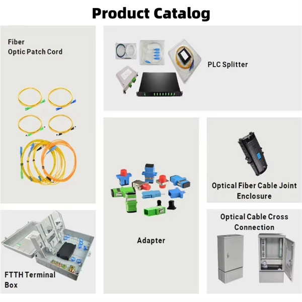
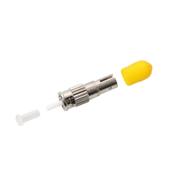
Fiber optic connectors can be categorized according to different standards such as utilization, fiber count, fiber mode, and transmission method. They are also divided into single-mode and multimode types based on their distinct characteristics. This guide will walk you through the most common fiber connector types, explaining their characteristics, advantages, and typical use cases. Whether you're planning an FTTH deployment, upgrading a data center, or working in telecom infrastructure, this guide will help you make informed decisions. Compared to Copper cables, Fiber connector types are incredibly varied. Where copper twisted pairs tend to terminate with an RJ45 plug, fiber optic connectors come in all sorts of shapes and sizes, with all manner of different use cases in mind. An optical fiber connector is used to join optical. With a wide variety of connector types available, choosing the right connector for your network can be challenging. Learn how each connector works, where it's used, and how to choose the right option for today's high-density, high-speed networks. It is a precise coupling device that joins fiber optic cables quickly, enabling faster connection and disconnection than splicing. The connector mechanically orients the fiber cores, allowing light to pass and travel through. In this guide, you'll explore various types of fiber optic cable connectors, each with unique features and best uses. We'll also provide practical advice.
[PDF]

Cable Trays* — Max two 24 in. (610 mm) wide by max 6 in. (151 mm) deep open-ladder cable tray with channel-shaped side rails formed of 0. 54 mm) thick aluminum or min 0. In practice, cable tray dimensions are a system of interrelated measurements —width, depth, length, and material thickness—that directly affect cable fill compliance, heat dissipation, structural loading, and long-term expandability. From an engineering standpoint, cable tray dimensions are not. Perforated Cable Tray System expertly constructed from high-grade stainless steel, offering exceptional durability and resistance to corrosion. With side height 100mm. A properly designed and installed cable tray system will provide. Studs — Wall framing to consist of wood studs or channel shaped steel studs. Wood studs to consist of nom 2 by 4 in. Additional studs shall be used to completely frame. Best Size: Here, deep trays (75mm to 150mm) are used since power cables are typically thick and heavy. Data cables, such as your Wi-Fi or computer ones, are extremely sensitive. They do not get hot; however, they do not like to hang or sag. In case a data cable folds in an excessive manner, the. ect the minimum bend ra-dius for cables as they exit the bottom of the cable tray. A rung spacing of 6 to 9 inches (150 to 230 mm) is preferable when the cable tray cont d for instrumentation and control applications that require additional protec eferred to support and protect numerous small.
[PDF]
Learn how to properly install a pigtail connector in just a few easy steps. No description has been added to this video. Enjoy the videos and music you love, upload original content, and share it all with friends, family, and the world on YouTube. Pigtail connections are most frequently used to ground a switch or electrical outlet and for electrical devices that need to connect to multiple circuit wires. They also come in handy to lengthen circuit wires that are too short to reach a device. A pigtail is composed of three strands of wire. A pigtail connector is a short length of insulated electrical wire that is pre-attached to a device, terminal, or fixture, serving as a flexible bridge between the fixed wiring system and the component. Whether you are a DIY enthusiast or someone facing an electrical issue, understanding how to replace a pigtail connector can be invaluable. This article will walk you through the necessary steps and provide. This is where quality automotive connector replacement steps in. Often, rather than pay thousands of dollars for an entire harness, you can simply replace the damaged connector by a careful de-pin/re-pin or an accurate wire repair. Want more automotive electrical wire repair videos? Click Here Hear. The National Electrical Code (NEC) requires a pigtail to be at least six inches long. Although this standard applies to house wiring, we can use the same for vehicle wiring.
[PDF]

This guide will walk you through the most common fiber connector types, explaining their characteristics, advantages, and typical use cases. Created by the Fiber Optic Association as an educational project to help document the history of the development of fiber optics for communications. Since I was involved in fiber optics starting in the late 1970s, much of this is from personal experiences and memories. Whether you're planning an FTTH deployment, upgrading a data center, or working in telecom infrastructure, this guide will help you make informed decisions. This is the FOA's Online Guide To Fiber Optics, Fiber Broadband & Premises Cabling. It includes almost a thousand pages of materials created by the FOA covering the basics to advanced topics on fiber optics and premises cabling. The goal of this website is educating students, users, designers. Fiber connectors, also called fiber optic cable connectors, are often used to link optical fibers where a connect or disconnect capability is needed. Fiber optic cable connectors come in many configurations and usages, and simplify fiber optic cable installation and maintenance greatly. A number of. This tutorial will provide a brief analysis of the current fiber optic connectors market and a detailed introduction to Fiber optic connectors. Fiber optic cables are increasingly replacing.
[PDF]
* Bronze alloy bolts shall have a minimum tensile strength of 70,000 pounds per square inch. ** Bolts, cap screws, nuts, flat washers, locknuts: 18-8 alloy. Qualified to meet or exceed all the nationally recognized standards, including ANSI C119. 4 and NEMA CC1, the DMC Power system raises the quality, safety and productivity standard. Other aluminum compression connectors are made from com-mercially pure high conductivity wrought aluminum. Select type of connector from those listed below and follow the indicated procedure. ** Belleville Washers: 302 alloy. EX: TPC600-4N4-AA-GS TYPE TPC-N-AA Terminal Connector A C FIG. 3 T Terminal is designed to connect to aluminum or copper pads. Pad conforms to NEMA standards. 56 © 2011, AFL, all rights reserved. PP-3-00479. This publication contains the following new or updated information. This list includes substantive updates only and is not intended to reflect all changes. Added information about using a Top Hat Rail, catalog number 141A-AHR45, with a Adapter Extension Module, catalog number 141C-X40. Examples. We have recently reviewed our company's bus torque chart and found some of the values are in line with the bolt mfg suggestions (i. - 1/2" - 3/4" bolts). I started to update our torque chart to match the.
[PDF]

Fiber optic connector pull test demonstration with real-time insertion loss monitoring. We use an optical loss tester to track signal stability every second while controlled tension is applied to the fiber. more. Fiber optic cable is surprisingly strong, durable and pliable; however, several best practices should be followed to ensure a successful cable installation. The below article explores the best practices and tools commonly used to pull fiber optic cable. The Future Ready Solutions Tools & Test. NEOFIBO TFTM-100N Vertical Fiber Optics Cable Tension Testing Machine The Cable Tensile Testing Machine is a precision mechanical measuring instrument designed to evaluate the tensile strength and elongation properties of various cables, wires, and fiber optic assemblies. Most fiber damage does not come from normal operation after the system is live. It happens during installation, when excessive pulling force, tight bends. Fiber optic connectors are designed to be connected and disconnected many times without affecting the optical performance of the fiber circuit. Optimal performance can be achieved by following the correct process for termination of the fiber circuit—a task which requires the use of a wide range of. The Fluke Networks JR-LEV-1 JackRapid Punch Down Tool is a cable termination tool that is designed to give technicians maximal efficiency in cable maintenance.
[PDF]

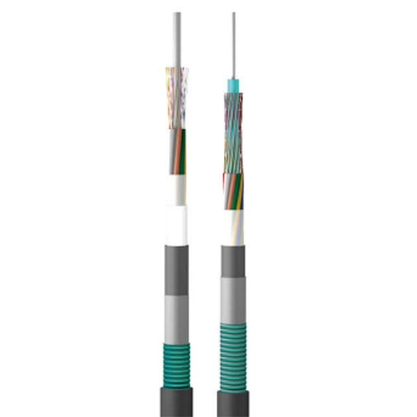
Since the earliest days of fiber optics, multimode cables have typically been color‑coded orange, black, or gray, while single‑mode cables are marked in yellow. For example, cable jacket color typically defines the fiber type, and can differ based on mode and performance level. These colors are typically chosen by industry standards bodies. However, there are some non-standardized colors and inconsistencies that you should be aware of. However, with the introduction of metallic connectors like FC and ST—whose bodies are difficult to color‑code—colored strain relief boots. Multimode fiber (MMF) is a kind of optical fiber mostly used in communication over short distances, for example, inside a building or for the campus. Multimode fiber optic cable has a larger core, typically 50 or 62. 5 microns that enables multiple light modes to be propagated. Because of this, more. Originally developed by the Electronic Industries Alliance (EIA) and the Telecommunications Industry Association (TIA), the TIA-598-D standard (formerly EIA/TIA-598) remains the most recognized color-coding system for optical fibers worldwide. On the right, the yellow patchcord indicates singlemode fiber and the blue connector means it is a regular PC polished connector, If it were an APC connector, it would be green. Perhaps nothing is.
[PDF]
Return-to-zero (RZ or RTZ) describes a line code used in telecommunicationssignals in which the signal drops (returns) to zero between pulses. This takes place even if a number of consecutive 0s or 1s occur in the signal. The signal is self-clocking. In digital communication systems, line encoding schemes are crucial for representing binary data efficiently and reliably. RZ (Return-to-Zero), NRZ (Non-Return-to-Zero), CRZ (Chirped Return-to-Zero), and CSRZ (Carrier-Suppressed Return-to-Zero) are distinct line coding methods, each with its own. Abstract—Analytical formulas for the power spectra of return-to-zero (RZ) optical signals generated by Mach–Zehnder (MZ) modulators are derived. This means that a separate clock does not need. The experiment aim of this experiment is to analyze the operation of Non-Return to Zero(NRZ), Return to Zero(RZ) and Pulse ration encoders and decoders. The setup created in OptSim is shown below: Each link.
[PDF]

The codes in Box 7 of your Form 1099-R indicate the type of distribution you received. Distributions from a governmental section 457(b) plan to a participant or beneficiary include all amounts that are paid from the plan. For more information, see Notice 2003-20 on page 894 of Internal Revenue Bulletin (IRB) 2003-19 at IRS. gov/pub/irs-irbs/irb03-19. Enter the information from your 1099-R exactly as. Use Code 1 only if the participant has not reached age 591/2, and you do not know if any of the exceptions under Code 2, 3, or 4 apply. However, use Code 1 even if the distribution is made for medical expenses, health insurance premiums, qualified higher education expenses, a first-time home. The IRS is permanently retiring the FIRE system. All electronic information return filing will move to IRIS (Information Returns Intake System). If you currently file through FIRE, you must transition to IRIS before the deadline. These 1099r codes descriptions are taken directly from the back of form 1099-R. Early distribution, no known exception (in most cases, under age 59½). Death – regardless of the age. The following tables contain 1099 Box Numbers. These numbers are assigned to vendors on the Maintain>Accounts Payable>Vendors>1099 Information tab.
[PDF]
Phase A is yellow, Phase B is green, and Phase C is red DC Bus: positive red, negative blue Simulates the logo color of the busbar Voltage Unit (kV) - Color AC 0. 4 - Yellow-brown AC 3 - Dark Green AC 6 - Navy Blue AC 10 - Crimson AC 13. 8~20-Light green AC 35 - Light. With SIRIUS, SENTRON, SIVACON and ALPHA, we offer an innovative portfolio for standard-compliant and demand-oriented applications. Efficient engineering tools and innovative cloud-based solutions can be flexibly tailored to individual requirements. com/system-certificates/ep). The. Double spacer for easy leveling and connecting on both sides (snubber. ). This document provides an overview of Intercable's product line of High Voltage extruded Busbars, the applicable geometry, attachment components as well as a summary of tests conducted per customer product validations. Holes are punched in the ends or mounting elements, which are protected from. IEC 60445 is one of the most widely used international standards for wiring colour codes - and understanding it can not only help to identify any wiring or electrical components quickly and reliably, but also improve compliance with safety regulations. When used, the set is heated on the busbar and then shrinks on the busbar, which plays the role of safety.
[PDF]

In this step-by-step guide, we will walk you through the process, ensuring that you can seamlessly connect your optical cable and enjoy a clear and uninterrupted audiovisual experience. Optical cables are becoming increasingly popular for transmitting high-quality. Optical audio cables can easily improve your TV's sound by connecting to external speakers. Learning how to connect an optical cable is easy, but there are a couple of gotchas that you should know. Here are the basics: Identify the optical output; if there's a protective plastic cap, remove it. The most common types are: The Toslink optical cable is a standard for transmitting digital audio signals. It uses a plastic or glass fiber to carry light signals from one. You can connect an older flat screen TV to ANY Stereo system, Surround Sound system, or Soundbar. This video shows you step by step how to make audio connections using an digital optical cable. You can use an optical connection even if your audio system does not have an optical socket, and by using. One of the easiest ways to achieve high-quality sound is to connect your TV to a home theater system or soundbar. Easily connect your optical audio cable to your TV! Follow our step-by-step guide for a hassle-free setup and enjoy crystal-clear sound. No wonder how to improve TV sound, right? When the sound is weak, for example, when using an analog sound source, then an optical audio cable possibly will be the.
[PDF]
The primary function of a fiber adapter panel is to provide a housing for fiber optic adapters or connectors. These adapters act as the interface between the terminated fiber ends and the active equipment, such as switches, routers, or servers. A fiber patch panel is a mounted enclosure—either rack-mounted or wall-mounted—used to terminate, manage, and interconnect multiple fiber optic cables. It acts as a hub for organizing splices and patch cords, streamlining fiber management and preserving signal integrity. This guide will focus on elucidating the aspects of the fiber patch panel, its accessories, the work done with such a device, and how to. Fiber optic networks are the backbone of fast, reliable internet and modern communications, but even the best fiber cables need the right connectors and patch panels to work efficiently. Connectors are the points where fiber cables link to devices, equipment, or other cables, and using the right. The fiber optic patch panel, also known as the fiber distribution panel, serves as the crucial component of the management of fiber optic cables. Also, the advantage of fiber optic patch panels is to reduce the loss of fiber optic transmission and facilitate engineers to troubleshoot. Serving as the network's centralized junction, it provides secure ports for both incoming and outgoing fibers, streamlining connection.
[PDF]
Step-by-step instructions on how to install fiber optic connectors like LC, SC, and ST. Includes tool recommendations, epoxy and polish method, and safety tips for installers and technicians. Even with sharing in efficiency, fiber connector installation is still an effort in which precision and safety form the central themes. A correct installation creates a low-loss, reliable connection essential for high-speed data transmission. While fiber optics enable speeds and distances copper can't match, the system's performance hinges. Next, we will introduce in detail the installation of several different types of fiber optic connectors. How To Connect Fiber Optic Cable To Connector? The connection methods for SC, FC, ST, and FT connectors with optical fibers are basically the same. Unlike foil strain gauges, fiber is often suitable for embedment. Sensuron's FOS offers hundreds to thousands of sensing points with a resolution of 1. 4 mm along a single sensing fiber. This video demonstrates the process of installing a fiber optic sensor to a substrate for measuring distributed mechanical strain. Fiber optic connectors are devices that join two fiber optic cables together, allowing the transmission of light signals with minimal loss. They come in various types, such as SC, LC, ST.
[PDF]
will introduce major upgrades to its Multi-Rail technology platform at ECOC 2025, targeting hyperscale optical transport with new efficiency, scale, and performance enhancements. Coherent Corp. SAXONBURG, PA, September 26, 2025 (GLOBE NEWSWIRE) – Coherent Corp. At the heart of the. SAXONBURG, Pa. At the heart of the. Simultaneously, coherent technology has emerged as the prevailing solution for Data Center Interconnection (DCI) applications, covering distances of 80~120km in the field of data communication. These evolving applications introduce new demands for coherent optical transceiver systems, steering the. Coherent optical module refers to a typically hot-pluggable coherent optical transceiver that uses coherent modulation (BPSK / QPSK / QAM) rather than amplitude modulation (RZ/ NRZ / PAM4) and is typically used in high-bandwidth data communications applications. Optical modules typically have an.
[PDF]