
This article compares typical cost ranges across speeds and transceiver types, explains why prices vary, and gives practical guidance for choosing the right optics for a given budget and performance requirement. This article helps network architects and procurement teams run a practical cost analysis for implementing Open RAN using pluggable optical modules across fronthaul and midhaul. All price bands below are market-observed ranges (OEM-branded vs. As per our latest research, the 25G Fronthaul Optical Module market size reached USD 1. 42 billion globally in 2024, demonstrating robust growth driven by the accelerating deployment of 5G wireless networks and expanding data center infrastructure. The market is projected to grow at a CAGR of 18. 7% from 2025 to 2033, reaching a forecasted value of USD 4. 47. The 5G fronthaul optical transceiver modules market is experiencing rapid evolution driven by the global rollout of 5G networks. These modules form the backbone of high-capacity, low-latency communication infrastructure essential for 5G deployment.
[PDF]

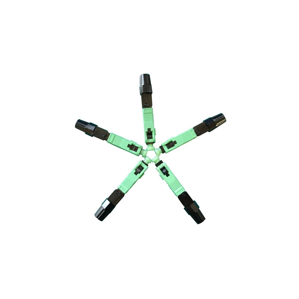
These general purpose fiber clamps provide easy means for incorporating glass or plastic optical fibers into optomechanical post assemblies or SM1-threaded components. The precision V-groove and rubber pad are designed to clamp onto the buffer of single mode or multimode fibers without damaging. Harwin supplies a range of surface-mount shield can clips to provide a straight-forward, easy-to-use board-level shielding solution. The combination of SMT clips with a shield can provides a simple and cost-effective method of shielding vulnerable or EMI-radiating board components. Harwin's shield. Check each product page for other buying options. 2-piece kit Fiber optical thermal stripper M8 & fiber optical cleaning clip compatible with bare fiber/bundle and ribbon fiber for 1-48 core dual heating mode and 8-level temperature regulation. Need help?. FPH Fiber Chucks and Holders are designed to terminate bare optical fibers and provide precise coupling and mounting within optical systems. Compatible strain relief boots and fiber clamps are also available. Clamps are larger than clips and designed to hold multiple cables and wires together. Blind plugs are used to close. 1-800-363-1992 Have any questions? Talk with us directly using LiveChat.
[PDF]
It involves encapsulating the optical chip in a metal box filled with inert gas (usually helium) to protect the optical elements from external environmental influences and enhance heat dissipation. COB, BOX, and TO-CAN packaging each offer unique advantages tailored to specific applications. COB packaging integrates components directly onto a PCB, enabling miniaturization and cost efficiency. BOX packaging seals optical chips in a metal enclosure with inert gas, ensuring long-term stability. The COB process refers to a technology that directly mounts bare chips onto a printed circuit board (PCB), connects them via gold wire bonding, and then encapsulates and protects the chips and wires using organic adhesive. Compared with conventional processes, the COB process offers high packaging. Box, COB, and TO can are currently the most prevalent packaging forms for optical components. Box packaging, also known as hermetic sealing, has a long history. Common optical device packaging methods include COB (chip-on-board packaging), BOX and coaxial packaging. What is COB technology? COB (Chip on board) is a form of packaging that directly bonds the. The invention provides an SFP28 SR optical module structure of a COB process, and belongs to the field of optical module structures. The micro-optical module comprises a shell, an unlocking mechanism, an EMI shielding structure, a circuit board, a micro-optical module arranged at one end of the.
[PDF]
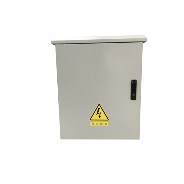
Huijue, a leading BESS manufacturer, offers top-performing lithium battery-powered storage solutions. Ideal for grids, commercial, and industrial applications, our systems seamlessly integrate and optimize renewable energy sources. Huijue Group's energy storage solutions (30 kWh to 30 MWh) cover cost management, backup power, and microgrids. To cope with the problem of no or difficult grid access for base stations, and in line with the policy trend of energy saving and emission reduction, Huijue Group has launched an. Founded in 2002, Huijue Group is a high-tech service provider integrating intelligent energy storage equipment and computer intelligent network communication system integration and application. Huijue Network's products are exported to Europe, North America, Southeast Asia and other countries and. Shanghai, China 5 years 523 staff Main categories: Home energy storage system, Telecom power supply, Energy Storage Batte. Huijue Group was established in 2002 and is a comprehensive high-tech group that integrates diversified development such as communications, the Internet of Things, and new energy. Huijue, a pioneer in Battery Energy Storage Site technology, stands. Since its establishment in 2002, Shanghai HuiJue Technologies Group Co. With its innovative technologies in the fields of intelligent network communication equipment and energy storage.
[PDF]

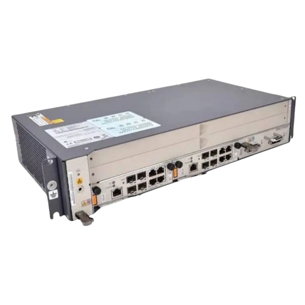
BBU end can be connected to CWDM coarse wavelength division multiplexer through CWDM color optical module and OS2 single mode optical fiber patch cord, and then transmitted to CWDM coarse wavelength division multiplexer with one or two optical fibers. The operation of base stations requires a large number of optical modules for interconnection between devices, and we will talk about the application of optical modules in mobile communication base stations. Communication base station is composed of machine room, base station, antenna, feeder. The base station can be divided into two modules: the RRU for transmitting signals and the BBU for processing signals. The BBU is small and exquisite, with low power consumption, while the RRU is large and has high power consumption. In 4G networks, the optical modules used to connect BBU and RRU are mainly gigabit to 10Gbit optical modules. In modern server racks, the wrong optical choice can silently tax performance: queues grow, link training becomes flaky, and operators end up swapping modules mid-quarter. In 5G networks, CPRI is also upgraded to eCPRI. Currently, 5G of the bearer network mainly uses 25Gbps optical.
[PDF]

Bit Error Rate (BER) is a critical performance metric in optical communications that measures the number of errors occurring in a transmitted data stream over a certain period. It is defined as the ratio of the number of bits received in error to the total number of bits transmitted. This ratio is most often expressed using scientific notation (e., 10⁻⁸. USI has industry-leading capabilities in high-speed signal integrity and power integrity (SI/PI) design, as well as advanced thermal simulation and optical simulation using Zemax. In addition, we have strong expertise in high-speed PCB design utilizing mSAP and substrate PCB technologies. USI also. Unlock AI-driven, actionable R&D insights for your next breakthrough. As optical links are increasingly used for high-speed data. Even a digital data transmission system is not totally error-free — statistical fluctuations related to noise influences cause a small percentage of the transmitted bits to be corrupted. The average fraction of incorrectly transmitted bits is called the bit error rate. Offers precise, cost-efficient optoelectronic signal and anomaly testing for high-speed transceivers. · Use control board and replaceable.
[PDF]

Continuous-wave operation (cw operation): The laser is continuously pumped and emits light continuously, either on a single resonator mode (→ single-frequency operation) or on multiple modes (see also: single-mode operation). How do optical. EML stands for Externally Modulated Laser (corrected from "External Modulated Laser"). Its basic principle is to supply a constant current to the laser diode, ensuring the LD emits continuous, stable light. An external electro-absorption modulator (EAM) then adjusts light transmittance to generate. A wavelength swept light source emits laser light with a continuously sweeping wavelength. It is suitable for shape measurement and displacement measurement utilizing OFDR (Optical Frequency Domain Reflectometry), an optical sensing method using the coherence of laser light. The transmitting interface inputs electrical signals of a certain bit rate, which are then processed by internal driver chips. Subsequently, the driver semiconductor laser. Industry pundits have recently speculated that demand for 100G/400G switches may take off in 2019, prompting optical transceiver module vendors to sample data center switches with high data transmission rates earlier than expected. As data center operators accelerate upgrades in preparation for 5G.
[PDF]

In this tutorial video, we will show you step-by-step how to safely and effectively remove an optocoupler from a circuit board using desoldering wick. We will walk you through the tools you will need, the proper technique for using the desoldering wick, and the precautions to take to av. more In. Whether you're replacing a faulty component, salvaging parts from an old board, or correcting a soldering mistake, knowing how to desolder effectively is essential. This guide will walk you through the tools, techniques, and best practices for desoldering components from a circuit board safely and. Desoldering is a process that removes the solder and components from a printed circuit board or any other type of electronic assembly. This is a meticulous process and it can easily damage the board, or the components, if not properly done. Thus, it is important to know how to desolder properly. If you're desoldering a battery from a circuit board, use flush cutters to cut each wire one-at-a-time to isolate the battery before you desolder the wires. Whenever possible, create an indirect path by soldering connectors onto the battery and the circuit board. This reduces the chance of an. Sorry, an unexpected error has occurred. Why Publish? The Ultimate Guide to Desoldering: From using desoldering irons to sketchily knocking breadboard components off on the side of a table, there are tons of ways to remove components from a circuit board.
[PDF]

Test the GFCI outlet by unplugging the ONT and plugging in a lamp, hairdryer or any corded electrical device you have. Still have no power? You'll need to reset the outlet. Check the two little buttons on the outlet. The following error logs are seen on Gen7 hardware resulting in loss of connectivity. BL-1084 Optical Module reset detected on slot 0 port 1 MCU version 0x19 (0x19) reset-count 51 (50) reset-reason 0x00000000 (0x0000000c). BL-1085. If that does not resolve your internet issue, you can follow these instructions to check the power to, or restart, your ONT. Not sure if you have an ONT? The video below can help you identify if you have one. What is an ONT? Are you a fiber customer? Learn how to identify your Optical Network. The transmit power of the optical module is too low or too high. Check whether an optical module that is certified for Huawei data center switches is installed on the optical interface. The CE series switches must use optical modules. In this article, we will focus on teaching you how to troubleshoot and solve the common three categories of optical module failure. First, the transmission class of the optical module fault investigation and solution method This type of optical module failure mainly includes port not UP, port. Resetting your Optical Network Terminal (ONT) can often resolve connectivity issues. Any FortiGates using optical fiber module. Clean any dust on the fiber patch or patch panel. Plug the SFP back in and assess.
[PDF]

As illustrated in typical SFP internal structure diagrams, the module's core components include an optical transmitter assembly (TOSA), laser driver, optical receiver assembly (ROSA)—some high-sensitivity modules (like L16. 2) use APD receivers, which require an additional booster. The optical module serves as a crucial component in optical fiber communication systems, operating at the physical layer, which is the lowest layer in the OSI model. Its primary function is to achieve optoelectronic conversion by converting electrical signals into optical signals and vice versa. Among various optical module form factors, SFP (Small Form-Factor Pluggable). The function of the optical module is to carry out the photoelectric and electro-optic conversion. In this article, ETU-LINK will introduce to you what are the core components of the optical module? 1. TOSA: Its main function is to convert electrical signals to optical. the embodiments of the present applicationprovide an optical emission module, an emission device, a detection device and a terminal, which can improve the energy density of a light spot formed by an emission light beam and improve the integration of the device. an embodiment of the present.
[PDF]
Optical Modules are hot swappable, and you do not need to power off the device when replacing Optical Modules. Optical Modules are electrostatic-sensitive components. In most enterprise networking environments, the ability to replace hardware without shutting down equipment is essential for maintaining uptime. Do not insert an optical module reversely. Gently pull the module latch or release ring, depending on the module design. Remove the module in a straight motion – do not twist or pull at an angle. Reapply the. Before you begin removing a transceiver from the router, ensure that you have taken the necessary precautions for safe handling of lasers (see Laser and LED Safety Guidelines and Warnings). Ensure that you have the following parts and tools available: The transceivers for the router are. An optical module implements optical-electrical conversion, enabling optical transmission between a DRH and other devices. Disconnecting the optical fibers interrupts the transmission of CPRI signals.
[PDF]

An optical module's actual transmit power measured by an optical power meter is lower than the nominal transmit power of the power module. The possible causes are: Bores of the optical module are contaminated. Stable optical power is the foundation of every high-capacity optical transport system. Even minor deviations—whether too high, too low, or unstable—can impact signal integrity, trigger service alarms, or interrupt traffic on DWDM, OTN, or long-haul optical line systems. This is the domain of Cell-to-Module (CTM) power loss, a series of. This paper reviews methods for reducing different optical and electrical loss mechanisms in PV modules and for increasing the optical gains in order to achieve higher CTM ratios. Various solutions for optimizing PV modules by means of simulations and experimental prototypes are recommended. Have you ever experienced an unexpected network outage due to the failure of an SFP/SFP+ optical transceiver? Network outages can bring your ability to communicate and work to a halt, and your IT team will likely be frantically looking for a solution. It is important to understand how to. This article provides an in-depth analysis of two key performance indicators of optical modules: transmitter power and receiver sensitivity. Transmitter power characterizes the average optical power output from the laser under rated conditions, while receiver sensitivity indicates the minimum.
[PDF]
There are a total of 379 Optical Products Manufacturers in Africa as of April 01, 2026. (Google Earth) file formats. 98% increase from 2023. 75%. Promoted | NEC XON and Smartoptics are introducing a new era of pluggable optical solutions for Africa. For years, African. This section provides a list of the top 10 Optical Module manufacturers, Website links, company profile, locations is provided for each company. Also provides a detailed product description of the Optical Module, including product introduction, history, purpose, principle, characteristics, types. As specialized fiber optic transceivers manufacturer, Star Computer Limited is located in Johannesbur, South Africa. The company was founded in 1999, at first we mainly made cable assemblies, later we expanded our business to various kinds of fiber optic transceivers, our transceiver products types. The rapid development of AIGC has promoted the demand for 800G optical modules, and the entire industrial chain involving optical components, optical modules, and optical communication equipment is expected to fully benefit. To help you choose the best partner, this article will analyze and. Avago Technologies (now part of Broadcom Inc. ) is a global leader in high-performance optical and networking components. Their family of Small Form Factor Pluggable (SFP) LC optical transceivers is designed to deliver reliable, scalable, and energy-efficient connectivity across enterprise, data.
[PDF]
In the photopic region, luminous efficacy peaks at 683 lumens per watt at 555 nm. In fact, the lumen is defined in terms of the power at 555 nm (frequency of 540 × 1012 Hz). Luminous efficacy is defined as the luminous flux produced per unit of power, usually electrical power, measured in lumen per watt (lm/W). It is explained how the overall efficacy of a lighting installation is often lower than that of the light source itself due to factors like light absorption in. Luminous efficacy is a measure of how efficiently a light source produces visible light. Depending on context, the power can be either the radiant flux of the source's output, or it can. The relative spectral responsivity of the human visual system was first defined by the Commission Internationale de l'Éclairage (CIE, the International Commission on Illumination) in 1924. The response of the eye as a function of frequency is called the luminous efficacy of the eye. It has been tabulated for both the light-adapted (photopic) case and the dark-adapted (scotopic) case. Source: Table 6-1 of.
[PDF]
Run the display device esn command to view the chassis serial number. The command format may vary depending on the. This document describes how to obtain the serial numbers of S series switches running V600. The serial numbers of devices are necessary for network construction and device maintenance. GigabitEthernet1/0/2 FINISAR CORP. FTLF1619P1BCxxxx PR7xxxx 2014-02-21 NO GigabitEthernet1/0/10. This topic describes the encapsulation types of optical modules on WDM products Small form-factor pluggable (SFP) optical modules are compact, hot-swappable, low-speed optical modules. They comply with the specifications defined in the multi-source agreement (MSA) and support synchronous optical. Here are the common commands to use to display hardware-related information on Huawei Routers. The inventory information such as serial number, product code,optical module,device, power,voltage,temperature,fan, CPU and memory are very important on operation and troubleshooting purposes. Your email. ALL DIMMING BALLASTS TO BE LUTRON ECOSYSTEM, ECOSYSTEM H-SERIES, OR HI-LUME 3D TYPE. TO CONFIRM ALL CIRCUITING REQUIREMENTS. ARCHITECT TO VERIFY QUANTITY, LOCATION & FINISH OF ALL CONTROLS. This paper presents an Echo State Network (ESN)-Driven joint decision strategy for a configurable security Non-Orthogonal Multiple Access (NOMA) optical communication system. To address security vulnerabilities, a configurable key iteration scheme is introduced, achieving temporal interleaving of.
[PDF]