
Precast concrete trench systems provide protection and easy access to power, communication, fiber optic, control, and signal wires and cables. Engineered precast trench is used in the power, utility, and transportation industries and can also be used in conjunction with catch basins, inlets, and. Completing Outside Cable Plant Installation. Underground cables are pulled in conduit that is buried underground, usually 1-1. 2 meters (3-4 feet) deep to reduce the likelihood of accidentally being dug up. In extreme cold climates, cables may need to be buried at greater depths where there. THE SOLID APPROACH TO TRENCHING. Made of a unique, patented. Trenwa is the original manufacturer of precast concrete trench and offers the broadest line of proven trench systems. Trusted by Industry Leaders: Trenwa has been a go-to partner for North American infrastructure projects for over for over 60 years. Request a quote today to see how our products can. Waskey's Precast Cable Trench System offers a durable, customizable solution for protecting and organizing critical infrastructure. If you need any help, be sure to reach out. Precast Concrete Trench for underground utility purposes. Primarily used for enclosure of electrical, communication, power cables, and piping.
[PDF]
In electric power systems and industrial automation, ANSI Device Numbers can be used to identify equipment and devices in a system such as relays, circuit breakers, or instruments. The device numbers are enumerated in ANSI/IEEE Standard C37.2 Standard for Electrical Power System Device Function Numbers, Acronyms, and Contact Designations. Many of these devices protect electrical. List of device numbers and acronyms• 1 - Master Element• 2 - Time-delay Starting or Closing Relay• 3 - Checking or Interlocking Relay, complete Sequence• 4 - Master Protective. A suffix letter or number may be used with the device number; for example, suffix N is used if the device is connected to a Neutral wire (example: 59N in a relay is used for protection against Neutral Displacement); and suffixe.
[PDF]

Cable trays play a key part in keeping fire protection systems working. Here is what they do: They Make Safe Paths for Fire System Wires Cable trays are made from materials that resist fire. They can help stop fire from spreading. Recognize electrical cable tray misuse that can lead to electric shock and arc-flash/blast events and fires caused by overheating. The use and installation of cable trays is covered by legally enforceable OSHA regulations in 29 CFR 1910. 305(a)(3), or comparable standards promulgated by States. Scope: Firestopping for busway, cable trays, cables, and trunking passing through walls in enclosed electrical installations. Where cables pass through shafts, walls, slabs, or enter electrical panels or cabinets, openings shall be tightly sealed with firestopping materials in accordance with. Cable trays can be part of a planned cable management system to support, route, protect, and provide a pathway for cable systems. Power, low voltage control, data, or telecommunications wiring distribution systems can be used with cable trays. 1 This section applies to cable trays utilized to support and route low voltage cables (telecom, security, A/V). No fire alarm cables will be permitted to be installed in cable trays. If a fire starts, the tray protects the wires inside from flames and.
[PDF]
Distance relays, also known as impedance relay, differ in principle from other forms of protection in that their performance is not governed by the magnitude of the current or voltage in the protected circuit but rather on the ratio of these two quantities.OverviewIn, a protective relay is a device designed to trip a when a is detected. The first protective relays were electromagnetic devices, relying on coils operating on moving par. Electromechanical protective relays operate by either, or. Unlike switching type electromechanical with fixed and usually ill-defined operating voltage thresholds. Electromechanical relays can be classified into several different types as follows: "Armature"-type relays have a pivoted lever supported on a hinge or knife-edge pivot, which carries a moving contact. These relays may.
[PDF]

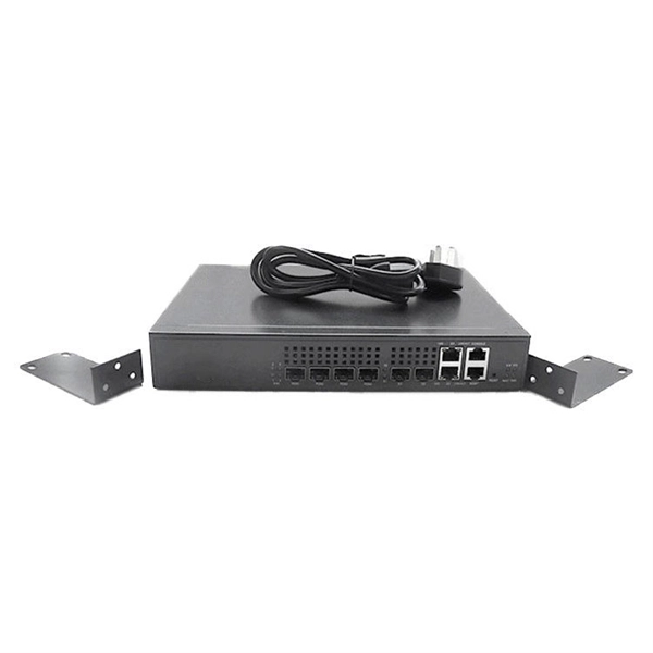
FS optical line protection switch features 1+1 backup and less than 15 ms fast switch to the standby fiber link that ensures business uninterrupted when malfunction occurs. An optical protection switch is a critical component in fiber optic communication systems designed to safeguard optical signals and infrastructure from damage due to power surges, signal overloads, or system failures. These switches ensure signal integrity, minimize downtime, and enhance network. 1+1 Optical Line Protection System for Fiber Protection, Bi-directional Protection in Dual Fiber, LC/UPC, Pluggable Module OLP (Optical Line Protection) is a device used in pairs, one at each end of the optical signal to protect network transmission line. OLP products include fiber optical line protection switches, optical bypass switches, optical cross connection, multi-channel. The FOSW-1x1 or 1x2 optical switch is based on opto-mechanical technology with proven reliability. OSW-W1x2 optical switch is a high performance electro-optical device, with low insertion loss (typic. In optical communication network, OLP monitors optical power of optical fiber and standby.
[PDF]

Generator protection relays are devices that detect abnormal operating conditions and isolate the generator from the system to prevent damage. These relays act as the first line of defense and are installed with strict adherence to IEC Standard for Protection Relays. Protecting generators from different electrical, mechanical, and thermal stresses is known as generator protection. To safeguard machines from overloads and unusual circumstances, preventive measures are required. Faults are inevitable even with effective design, construction, and operation. Below is an overview of the different types of relays used in generator systems, their functions, and their specific applications. Electromagnetic relays use. Generator Protections are broadly classified into three types: Class A, B and C. Class A covers all electrical protections for faults within the generating unit in which generator field breaker, generator breaker and turbine should be tripped. What Are Generator Protection Relays? Generator protection. There are various protection relays and those are used for protection against a wide variety of conditions. The fundamental principles that are covered in this course are equally applicable to. IEEE C37. 2 defines the IEEE “numerical” function designation for all protective relay functions. This presentation primarily uses the designations from the Beckwith M-3425A relay, which in most cases follows IEEE C37.
[PDF]

The National Electrical Code (NEC) has established eight levels of fire resistance for fiber optic cables. These levels are based on the time it takes for a cable to burn through or melt. Corning Optical Communications manufactures quality flame retardant optical fiber cables for indoor applications, which comply with the requirements of the National Electric Code® (NEC® 2023) published by the National Fire Protection Agency (NFPA). To ensure compliance to these requirements, a. Understanding the listing requirements of fire alarm circuit cables can help you make sense of the cable alphabet soup. Here are some highlights from Part IV of Article 770. There's plenty of "expansion room" built into Article 770. Part I ends with Section 770. 44. Cabling Installation & Maintenance - Classes 1, 2, 3, and 4, communications, fire alarm, and optical fiber cables are all addressed in the NEC. By Stanley Kaufman, PhD, CableSafe Inc. UL Solutions' long-standing history in certification and Standards development makes us a trusted thought leader in the. Understanding the fire ratings and jacket options for fiber optic cables is crucial for ensuring optimal performance and safety. This technical guide will provide a comprehensive overview of these factors, their implications on cable resilience and transmission, and tips for making informed.
[PDF]
This is the FOA's Online Guide To Fiber Optics, Fiber Broadband & Premises Cabling. With 19+ years of experience installing fiber-optic cables at over 20,000 locations, we've seen how prices vary based on cable type, project scope, and installation complexity. Fiber-optic cable materials typically cost $1 to $6 per linear foot, depending on fiber count and cable type. Main cost drivers include cable grade (indoor vs outdoor, armoured), distance, and labor for trenching, splicing, and termination. This guide presents ranges in USD and practical price estimates to help. Fiber optic cables are essential components in today's broadband, FTTx, and data center networks. Whether you're planning a national fiber rollout or sourcing cables for enterprise infrastructure, understanding how fiber optic cable pricing works can help you budget more effectively and make better. We have included Per Foot conversions for reference (1 Meter ≈ 3. Best For. * Disclaimer: Prices fluctuate based on raw material indices (Glass/Copper/Polymer) and cable core count (e. These cables, constructed with glass or plastic fibers, transmit data through light pulses, offering.
[PDF]

This guide provides clear cost ranges in USD and practical pricing details for U. Typical cost range for a single relay is $2–$150 depending on type and rating. Buyers typically pay a range for relays, and cost is driven by relay type, coil voltage, contact rating, and packaging. This guide presents practical price estimates in USD, with low–average–high ranges and real-world factors that affect total cost. Assumptions: region, specs, labor hours. Relays. The SEL-351 Protection System has built-in Ethernet and IEEE C37. 118 synchrophasors, and is ideal for directional overcurrent applications. Optional Mirrored Bits communications and power quality monitoring add flexibility to solutions. The SEL-351 is the protection standard for utility and. Buyers typically pay a modest amount for small signal relays and higher sums for industrial or specialty units. The main cost drivers are the relay category (signal, automotive, or industrial), quantity, and installation requirements. Although failure of a protective relay system may have severe local or regional impacts, most protective relay systems are not required to operate to prove they are in working order. Ensuring that. What are Protection Relays and How Do They Work? Protection relays are specialized devices designed to detect abnormal conditions in electrical systems and initiate appropriate actions to protect equipment and personnel. These intelligent sentinels continuously monitor electrical parameters and.
[PDF]

This handbook covers the code of practice in protection circuitry including standard lead and device numbers, mode of connections at terminal strips, colour codes in multicore cables, dos and donts in execution. Also principles of various protective relays and schemes including special protection. Read this document and the documents listed in the additional resources section about installation, configuration, and operation of this equipment before you install, configure, operate, or maintain this product. Users are required to familiarize themselves with installation and wiring instructions. presentation of protection and control relaying. The report will identify methodology behind these practices, present issues raised by the integration of microprocessor relays and the internal logic and external communication configurations, ying. The objective of this presentation is to convey a basic understanding of protective relays to an audience of engineers already familiar with low voltage protective device coordination. HT panel protection relay. The HT power supply is received from GO switch and distributed to the. The handbook for protection engineers includes guidelines on protective circuitry, protective relay principles, and testing procedures for switchgear and relays. It covers standard codes, wiring practices, and norms for protecting generators, transformers, and lines, and provides detailed.
[PDF]

A new updated course will be released for sale during the spring of 2026. SFS 6002 Electrical safety -course is mandatory in Finland for all persons involved in electrical works: installers, managers, assistants etc. The course is valid for 5 years and shall be renewed to maintain the. Electrical qualification 1 (Electrical Safety Act 1435/2016 Section 66) The holder of electrical qualification 1 may work as an electrical work supervisor and supervisor of operations in all electrical and operational work. These regulations lay down binding requirements, which cover e. A person who builds, repairs or maintains electrical installations, or repairs and maintains electrical appliances must be professionally qualified, and Tukes must be notified before any such operations begin. The operators are called electrical or lift contractors. A company or a natural person. Electrical safety is not just a legal requirement – it's part of everyday workplace safety. Cad Sä Oy has developed the Electricity Passport, a new training model in which SFS 6002 training is carefully tailored to the specific electrical tasks each participant will perform in their project. The. Finnish electrical safety card (Sähkötyöturvallisuuskortti SFS 6002) is intended for people working in the maintenance and servicing of electrical installations, machines and equipment up to 1000 V in Finland.
[PDF]

While nonarmored fiber optic cables don't require grounding due to their nonconductive properties, grounding is crucial when using armored fiber optic cables. Therefore, it is important to build a lightning protection system for fiber optic cables. How to Protect Fiber Optic Cable From Lightning? The major purpose of lightning protection systems is to conduct the high current lightning discharges safely into the Earth/ground. There are two main lightning. Fiber optic cable transmits data as light through glass or plastic strands, which means the fiber core itself carries no electrical current and requires no grounding. However, this does not mean every fiber optic installation is exempt from grounding requirements. Lightning-induced surges can travel through power lines, telecommunication lines, or nearby metallic structures and pose a. There are two main lightning protection grounding solutions in fiber networks, namely intermediate grounding and terminal grounding. These solutions use two ways of grounding for optical cable links both in domestic and foreign standards. However, because fiber optic cable has strengthened core, especially the direct-buried fiber optic cable has armoring layer.
[PDF]

87N high-impedance protection requires special class × current transformer cores with equal transformation ratios. The 7SJ60 relay can alternatively be connected in series with the 7UT613 relay to save this CT core. Earth faults on the secondary side are detected by current relay 51N. However, it has to be time-graded against downstream feeder protection relays. Primary circuit-breaker and relay may be replaced by fuses. Go back to contents ↑. Relay 7UT612provides numerical ratio and vector group adaptation. Matching transformers as used with traditional relays are therefore no longer applicable. Line CTs are to be connected to separate stabilizing inputs of the differential relay 87T in order to ensure stability in the event of line through-fault currents. Relay 7UT613provides numerical ratio and vector group adaptation. Go back to contents ↑. The directional functions 67 and 67N do not apply for cases where the transformers are equipped with the transformer differential relays 87T. Go back to contents ↑.
[PDF]

The K factor (or zero-sequence compensation factor) adjusts the measured impedance for the phase-to-ground fault loop by accounting for the contribution of zero-sequence currents. This compensation is critical because zero-sequence current introduces an offset in the fault impedance. The following Terms are used in protective relaying: 1. Fault Clearing Time 5. Drop Out or Reset value 8. Sealing Relay or holding Relay 10. Hermetically sealed, corrosion resistant metal can. Detail specifications and ordering data appear on the Data Sheet below. NewElec's KA, KB & KC Series relays provide robust and dependable motor protection relays designed to safeguard critical motors in a wide range of industrial applications. Fixed thermal curves (Class 15 Cold - Class 5 Hot) with thermal pre-loading, match the Hot and Cold stall times of the motor during operation. The KA relay is mains powered. The protection and control devices in electrical equipment can be referred to by numbers, with appropriate suffix letters when necessary, according to the functions they perform. These numbers are based on a system that is adopted by a standard for automatic switchgear by Institute of Electrical.
[PDF]
Pilot-wire relaying is an adaptation of the principle of differential relaying to line protection and functions to provide high-speed clearing of the line for faults anywhere on the line. Pilots include wire pilot (us.
[PDF]


