An Ethernet splitter consists of two RJ45 jacks, one on each side. These jacks are used to connect the Ethernet cable to the splitter. Depending on the type of splitter you have, there may also be other ports or connectors that need to be connected as well. A wiring diagram for an Ethernet splitter can make the installation process a breeze. It does not increase speed or create extra bandwidth. It simply divides signal pairs. This tool works best in basic setups where running another cable is not possible. An Ethernet splitter. An Ethernet Splitter works by separating a single line into two or more outgoing lines, allowing multiple users to draw from the same source without affecting bandwidth. You may also want to know: Are Bing and Yahoo the Same? · Are Sony and Murata Partners? The term “Ethernet splitter” is often. Repeat step 2 to connect a second Network Device to the Cable Adapter. To view manuals, FAQs, videos, drivers, downloads, technical drawings, and more, visit www. to an existing Network. Scenario: A company has two offices (A and B). A single CAT5 Ethernet drop.
[PDF]
Free electrical calculators for wire sizing, voltage drop, load calculations, conduit fill & power factor. NEC compliant tools for electricians & engineers. In this guide, we'll break down everything you need to know to install a distribution box correctly and confidently. Choose the right box based on environment (indoor/outdoor), load capacity, and durability. Check for proper IP/NEMA ratings and material quality. Ensure safe placement: install in. Professional electrical wire sizing tool based on National Electrical Code (NEC) standards. Calculate proper wire gauge, voltage drop, and ampacity for safe electrical installations. Input your electrical parameters to get accurate wire size. Pro Insight: A well-planned distribution box feels like a silent partner—you only notice it when something's wrong. Our goal? Make sure you never notice it. Before we dive into calculations, let's get familiar with a few essentials: 1. Create accurate bids and win more projects with automated formulas. The sizing requirements for pull boxes, junction boxes, handhole enclosures, and conduit bodies exist to prevent conductor insulation damage. Those requirements are in 314. 28, and they apply to all conductors 4 AWG and larger (Fig. To illustrate how these requirements prevent conductor. Estimate wire ampacity with derating factors for temperature and conduit fill. Reference tool based on NEC guidelines. It is NOT a substitute for professional.
[PDF]
The 11-in-1 Screwdriver includes the 8 bits and 3 nut drivers most requested by professionals. The bit prevents bit wear from hardened screws and extends bit life when fastening specialty screws found in elec.
[PDF]

A neat, well-organized subpanel bundles wires to conserve space and improve access. Ideally, wire groups are installed in layers and wires are bent at right angles to buses or breakers. Label short sheathing sections (slugs) to indicate which circuits wires serve. Choose the right box based on environment (indoor/outdoor), load capacity, and durability. Check for proper IP/NEMA ratings and material quality. Ensure safe placement: install in. Welcome to this live training session! ⚡ In today's tutorial, I'll be demonstrating how to arrange cables neatly inside a distribution bo. more See what others said about this video while it was live. Wire color: The neutral wire is blue, and the color of the phase wire (A phase is yellow, B phase is green, and C phase is red). It consists of various protective and control devices for electricity distribution in a building. 📌At the top, there are main circuit breakers and residual current devices (#RCDs), which protect against overcurrent and leakage currents. 📌The middle section includes an electric energy meter that. Wiring distribution panels serve as the central hub and nerve center, routing power from the main service feed to multiple circuits. When setting up such a significant component of industrial, commercial, and utility applications, it's essential to get everything right. When wiring distribution.
[PDF]

Wiring Direction: Wiring between the main circuit breaker and each branch circuit breaker in the box generally goes on the left, and the wiring out of the distribution box generally goes on the right. Binding Requirements: The wires should be bound with. Learn how to wire a distribution box step by step! This video shows real on-site footage of electrical installation, demonstrating safe and standardized wiring methods used by professionals. Whether you're a professional or a DIY enthusiast, understanding the correct procedure can prevent accidents and ensure optimal performance. This guide provides step-by-step. Hey, in this article we are going to see the Single Phase Distribution Box Wiring Diagram and Connection Procedure. A distribution board or distribution box is where the main power supply is distributed to multiple loads. Students utilize various electrical components, including circuit breakers and cables, and are guided to apply. Correct wiring methods for circuit breakers within distribution boxes are fundamental to ensuring electrical safety and compliance with established codes. The distinction between 1P and 2P circuit breakers plays a pivotal role in determining the appropriate protection level for various circuits. Connection method: Each switch takes a wire from the incoming point and connects it to the incoming end of the switch, or uses parallel connection to reduce the difficulty of wiring.
[PDF]

Download new and previously released drivers including support software, bios, utilities, firmware and patches for Intel products. trol I/O is desired. The Q-SYS Core 24f satisfies a broad spectrum of application needs from meeting room environments, conferencing systems, retail establishments, houses of worship, judicial environments, education institutions and other general purpose pro essing applications. A Core 24f may be. That change is why correct leads and connections matter for system stability and lifespan. Please sign in or register for an Intel account. Automatically update your drivers and software Use this tool to identify your products and get driver and. Purpose: This connector serves as the main junction, transmitting essential electrical currents from the supply unit to the motherboard. Design: It features a distinct arrangement of multiple connectors, each designated for specific functions, ensuring balanced and stable power distribution. Product replacement Get replacements and find substitutions for discontinued Schneider Electric products. Where to buy Search our network of verified distributors with over 15,000 sales outlets. Communications bus and supply power terminal blocks, functions, ratings, requirements, and cables provides information about the functions, ratings, and requirements for the communication bus and supply power terminals; and guidelines for wire sizes, cable types, and cable lengths when wiring the.
[PDF]
The soft starter wiring diagram typically includes information about the power supply, motor connections, control circuit, and bypass arrangement. It helps in understanding the complete wiring arrangement and makes it easier to troubleshoot any potential issues. See Technical Data TD03900001E. We are guided by our commitment to do business right, world's most urgent power management challenges. A proper wiring diagram is crucial to ensure the soft starter functions effectively and protects the motor from any kind of damage. Whether you're a professional electrician or a DIY enthusiast, this detailed wiring diagram and installation guide will help you understand the c. more. Soft starters are widely used to reduce the current surge when devices are started and to provide ramped acceleration to motors. The use of soft starters can reduce energy costs by up to 15%, as well as providing protection from damage caused by voltage sags or electrical faults. Connecting the soft starter to a wye motor inserts the SCRs directly in the line wiring, referred to as "In Line" wiring. If the motor is hard. If you're looking to install a soft start system in your electrical setup, it's crucial to understand the wiring diagram that goes along with it. A soft start system is designed to gradually increase the voltage and torque to a motor, reducing the initial inrush current and protecting both the.
[PDF]
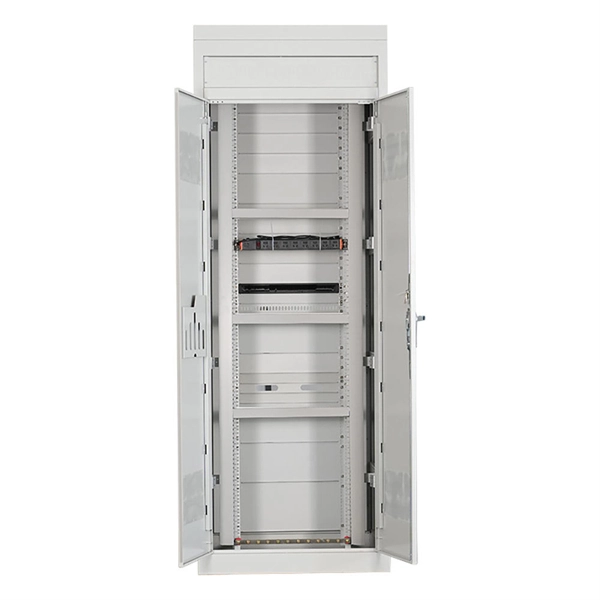
This comprehensive guide is intended to shed light on the various aspects of the PZ30 distribution box, including its design, components, functionality, and installation procedures. The PZ30 lighting distribution box plays a crucial role in this process, providing a centralized hub for managing and protecting electrical circuits in both residential and commercial settings. With modern aesthetics, safety-focused construction, and user-friendly features, it meets the needs of diverse applications. This versatile unit features a robust construction with high-quality thermoplastic materials, offering excellent protection against electrical. The PZ30 distribution box is a specialized electrical enclosure designed for single-pole circuit breakers, offering safe and organized electrical distribution in residential and commercial systems. The box features. This article details the features, installation methods, and user experience of the chint pz series nx household 30a circuit breaker distribution box. One of the key benefits of the PZ30 series is its modular design, which allows for flexible.
[PDF]

Wiring an electrical panel box can seem like a daunting task, but with the right knowledge and tools, it can be done successfully. In this guide, we will provide you with a step-by-step process to help you wire an electrical panel box safely and efficiently. Distribution Board or DB is an electricity supply system or a common enclosure that distributes the electrical power feed into subcircuits. It includes isolator, RCCB (Residual current circuit breaker) or RCD (Residual-current device) devices, protective fuses or MCB's (Miniature Circuit Breaker). This book serves as a concise guide for learners interested in basic electrical house wiring concepts. It provides practical instructions for various electrical configurations and connections, emphasizing the importance of safety and proper installation. Additionally, it introduces essential. The Guidelines For Electrical Wiring In Residential Buildings has been prepared as a wiring guide for all Wiremen and Electrical Contractors for undertaking electrical wiring in residential buildings to conform to the Electricity Regulations 1994. The Guidelines are prepared in a concise and. An electrical panel box, also known as a breaker box or a distribution board, is a crucial component of any electrical system. All the electrical sub circuits are originated from a Distribution Board. To understand how a breaker box works, it is helpful to.
[PDF]

We will look at how to interpret PLC LED status indicators for digital inputs and outputs and how to perform troubleshooting tests using a Digital Multimeter. This section includes the block diagram of the DI 16x24VDC ST module with the terminal assignments for a 1-wire connection. Information on wiring the BaseUnit can be found in the system manual ET 200SP distributed I/O system. The load group of the module must begin with a light-colored BaseUnit. How to wire real-world signals into the Logo's digital inputs to detect whether a machine is running. Covers stack lights, door sensors, relay contacts, and proximity switches — with a complete wire diagram and step-by-step instructions for both electrical engineers and IT teams. You have a Siemens. PLC and DCS control systems Wiring Diagrams for Digital Input (DI), Digital Output (DO), Analog Input (AI), and Analog Output (AO) signals. be responsible or liable for indirect or consequential damages resulting from the use or application of this equipment. The examples and diagrams in this manual are included solely for illustrative purposes. Because of the many variables and requirements. This manual contains information that is necessary to use the NX-series Digital I/O Unit. PLC programs rarely cause failures, so in this article, we'll assume that there are no program errors and that the fault originates in the.
[PDF]

Solar energy offers data centers a path to reduce their carbon footprint and operational expenses. Major tech companies like Google and Apple are already leading the way, demonstrating that solar-powered data centers are environmentally responsible and economically viable. Data centers are the backbone of our digital world, powering everything from streaming services and cloud storage to remote work platforms and IoT devices. As our reliance on digital infrastructure grows, so does the energy consumption of these mission-critical facilities. Currently, data centers. Solar offers clean power at predictable costs, can be built fast at many scales, and pairs well with batteries to deliver reliability. In this article, we explain why data centers use so much energy, how solar powers data centers, how batteries and microgrids keep servers online, and why these. 2022 to 35 gigawatts (GW) in 2030. The United States accounts f d tap into suitable energy sources. Renewable energy is the answer, but it must be cost-efective, able to meet enormous demand without inte zed by explosive growth and demand. The emergence of AI, data streaming, cloud computing, and.
[PDF]
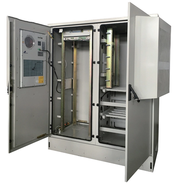
Papua New Guinea's rugged terrain and growing energy demands make outdoor energy storage cabinets a critical component for reliable power distribution. This article explores the unique requirements, technological advancements, and trusted manufacturers serving this dynamic market. This article explores how customized lithium battery systems address remote electrification, mining operations, and renewable integration while boosting sustainability. However, high temperatures and humidity pose challenges for battery longevity. This is where liquid cooling plate technology becomes. Summary: Papua New Guinea's growing energy demands require tailored battery storage systems to support renewable integration, rural electrification, and industrial growth. This article explores how customized energy storage solutions address local challenges, backed by case studies and industry. The project encompasses the construction of a solar and battery energy storage system (BESS) minigrid to be built on the island of Buka, within the Bougainville region. It will address the electricity needs of the region, which relies heavily on diesel generators. The deadline for applications is. Designed for remote locations, it integrates solar controllers, inverters, and lithium battery packs to ensure stable and continuous power for telecom equipment, surveillance systems, and off. Design engineers or buyers might want to check out various Lithium Battery Storage Cabinet factory &.
[PDF]

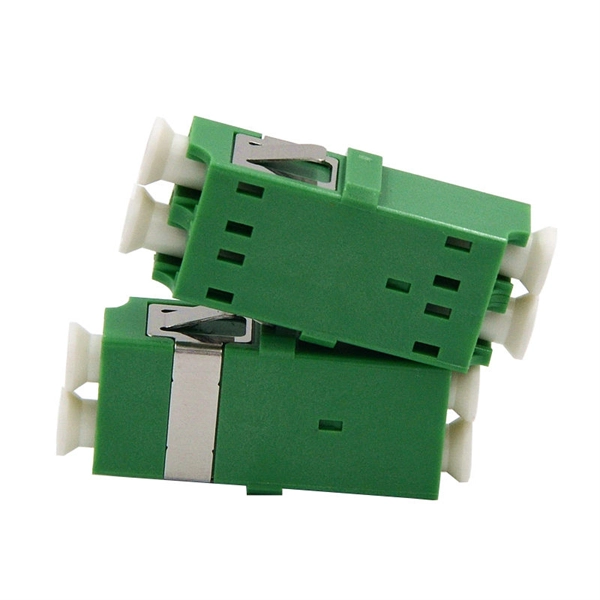
The complete process for terminating cable runs at a patch panel, from mounting and cable management to punch-down, labeling, and testing every port. To wire a patch panel: Mount the panel in your rack. If you're still deciding which panel style fits your site (keystone vs punch‑down vs pass‑through), start with How to choose a patch panel and come back here once the hardware is locked in. 60-second answer If you want reliable results, the winning recipe is simple: keep pair twists tight right up. Network patch panel, cable manager, network cable, wire stripper, crimping tool, zip ties. Use a small yellow tool or wire stripper to remove the outer jacket of the network cable. Cut off the cross-shaped skeleton of the Cat6 patch cord. Insert. Patch panels make cable management and network organization very easy over long periods of time, but you'll need to wire the panels in order to put them into your network. Not to worry, this guide will walk you through the whole process. Before you jump into the task, ensure that you have the. Testing a patch panel is an essential task to ensure the reliability and efficiency of a network infrastructure. The process verifies the end-to-end connection, ensuring the cable is properly terminated at the wall jack and at the distribution point, such as a switch or patch panel.
[PDF]

This handbook covers the code of practice in protection circuitry including standard lead and device numbers, mode of connections at terminal strips, colour codes in multicore cables, dos and donts in execution. Also principles of various protective relays and schemes including special protection. Read this document and the documents listed in the additional resources section about installation, configuration, and operation of this equipment before you install, configure, operate, or maintain this product. Users are required to familiarize themselves with installation and wiring instructions. presentation of protection and control relaying. The report will identify methodology behind these practices, present issues raised by the integration of microprocessor relays and the internal logic and external communication configurations, ying. The objective of this presentation is to convey a basic understanding of protective relays to an audience of engineers already familiar with low voltage protective device coordination. HT panel protection relay. The HT power supply is received from GO switch and distributed to the. The handbook for protection engineers includes guidelines on protective circuitry, protective relay principles, and testing procedures for switchgear and relays. It covers standard codes, wiring practices, and norms for protecting generators, transformers, and lines, and provides detailed.
[PDF]

Whether you're an electrician or a DIY enthusiast, this tutorial will help you understand the fundamentals of wiring a distribution box for a residential setup. The diagram of the distribution board's wiring shows exactly how each circuit is wired and connected. What is Distribution Board? Distribution board. A distribution box is the heart of any electrical system. It takes the incoming power and safely distributes it to different circuits throughout your building. Whether in a home or an industrial facility, this box keeps your electrical setup organized, functional, and efficient. However, the key to. In this guide, we will break down the key elements involved in connecting the main power supply to your home, providing a clear path for a successful setup. We will focus on the critical parts of the system, from basic components to step-by-step assembly procedures. It serves as a central hub for distributing electricity throughout a building, ensuring that power is delivered safely and efficiently to all the required locations.
[PDF]