FiberMall MPO16 APC Y Splitter Cables 10m are designed for 800G QSFP-DD/OSFP DR8/OSFP XDR8 optics direct connection and support 800G transmission for Hyperscale Data Centers. Multimode PLC Splitter is a passive optical device used to split incoming signals into two or more output signals. They're capable of operating over a broad wavelength range from 650 nm to 1350 nm (Typ. 650nm, 850nm and 1300/1310nm). 5/125 (OM1, OM2, OM3 and. High-Quality Construction: This Fiber Optic PLC Splitter is manufactured by UT-KING, a reputable brand known for its reliable products, ensuring a durable and long-lasting performance. Optimized for FTTH Solutions: Designed for use in Fiber-to-the-Home (FTTH) applications, this 1x2 OM3 PLC Splitter. Optical coupler is an optical device that combines or splits power from optical fibers. Note: All insertion loss and insertion loss referenced without connectors. Takfly, established in 2000, has been manufacturing. Optional split ration 1:99, 2:98, 5:95, 10:90, 20:80. USource OM3 Fiber Coupler is a 1x2 or 1x3 passvie optical multimode splitter based on FBT (Fused Biconic Taper) technology, packaged in mini ABS box module or steel tube, split into different rations 1:99, 2:98, 50:50, 10:90, 20:80.
[PDF]

Given the access to a fusion splicer, you can splice the pigtail right onto the cable in a minute or less, which greatly speeds the splicing and saves significant time and cost spent on field termination. A fiber optic pigtail is a short length of optical fiber cable with a factory-terminated connector on one end and a bare, exposed fiber on the other. Unlike a patch cord—which has connectors on both ends—the bare fiber end of a pigtail is designed to be permanently spliced (either by fusion or. The Contractor tasked to perform testing or splicing on any fiber optic cable will follow these testing standards to fulfill their contractual obligations. The Contractor must utilize the correct equipment and testing techniques to gain acceptance, or the work cannot be approved. While for mechanical fiber optic pigtail splicing, it precisely holds a fiber optic pigtail. Fiber optic fusion splicing is on the rise and Corning's Pigtailed Splice Cassettes enable faster field splicing and easy modular management of connectorization within the housing. Pre-routed and preloaded, pigtailed splice cassettes reduce installation time by up to 40%. Today, fusion splicing. Next, we will introduce three common types: SC, FC, ST fiber optic pigtails. 5mm pre-radiused ferrule which is made of zirconia or stainless alloy.
[PDF]

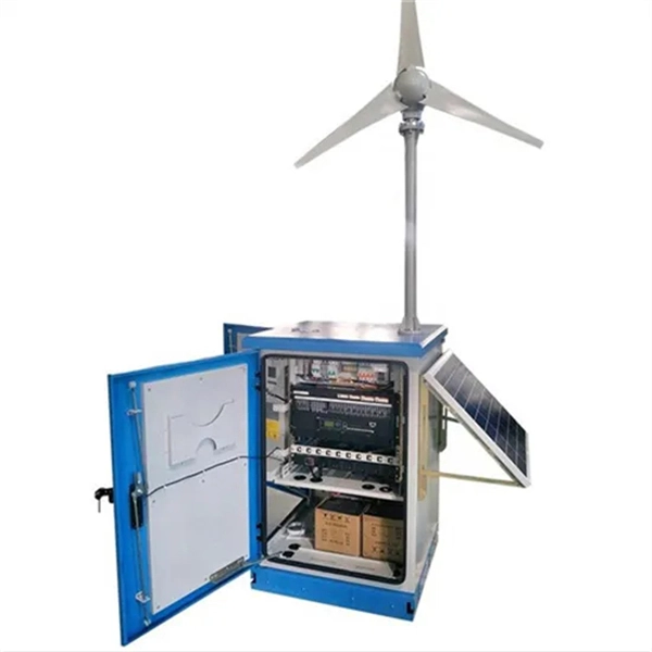
The typical setup time for a standard rapid deployment telecom tower ranges from 15 to 60 minutes once the unit arrives on site. However, complex installations requiring guy wires, heavy payloads, or difficult terrain can extend this window to 2-4 hours. How Should You Prepare for Installing Fiber Optic Internet? Before installing fiber optic internet, ensure your business location is ready. Site Planning and Design: This phase involves assessing the need for a new mobile site, selecting a suitable location, and designing the layout of the infrastructure. Conduct radio frequency (RF) planning and coverage analysis to determine areas with poor or no signal. Analyze user demand and. Equipment installation: Once the site is prepared, the equipment can be installed. This includes installing the telecom equipment in the cabinets, setting up the antennas, and running the cables. Testing and commissioning: Once the equipment is installed, it needs to be tested and commissioned to. Assuming the design is completed, we're looking at the process of physically installing and completing the network, turning the design into an operating system. Since. How long does it take to install fiber optic internet? The time it takes to install fiber optic internet depends on your home's layout and existing infrastructure. Will the technician dig up my yard to install fiber optic internet? Your fiber technician will need to either bury the fiber in your.
[PDF]

In the 2020 NEC ®, no more than 18 inches of cable length is allowed between the cable entry to the box and the closest cable support (see image). Below is a preview of the NEC®. ORG for the complete code section. The previous code language could technically allow an unlimited length of coiled up NM cable inside the wall as long as it was secured within 12 inches of the box. This code is based upon the type of box, wires, wire sizes, wire clamps and conduit fittings. Adjustments are made for the ground wire as you will see in the. Calculate and select the right number and spacing of cables for junction boxes using NEC guidelines to ensure safe, code-compliant electrical installations. This step keeps your project safe and. According to the National Electrical Code (NEC), the conductor must be long enough to extend outside the box's opening. This length allows enough room to connect, splice, or terminate wires without strain or damage. If wires are too short, they may fail inspection or create hazards during. The length of wire left inside an electrical box is a matter of strict compliance, safety, and functionality. Having the correct amount of slack ensures that future maintenance, repairs, or device replacements can be performed without difficulty. Proper electrical box fill calculations are critical for code compliance and safety in both residential and commercial installations.
[PDF]

The typical specification range of return loss of a fiber connector is -15 dB to -60 dB. Return loss is also known as reflection loss. It indicates the amount of signal reflected back to the transmitting end. Return loss refers to the power loss caused by the reflection of part of the signal back to the signal source during transmission due to the discontinuity of the transmission. Insertion loss, also known as attenuation, is the loss of optical power that occurs when light passes through a fiber optic connector. It is caused by factors such as misalignment, air gaps, and imperfections in the connector components. The lower the insertion loss, the better the performance of. Reflectance (which has also been called "back reflection" or optical return loss) of a connection is the amount of light that is reflected back up the fiber toward the source by light reflections off the interface of the polished end surface of the mated connectors and air. It is also called. Insertion Loss (IL) is the amount of optical power lost as the signal travels from one point to another in a fiber optic link, usually across connectors or splices. Formula for. In optical fiber communication, insertion loss and return loss are two important parameters to evaluate the quality of interfaces between some optical fiber components, such as optical fiber connector, fiber patch cable, pigtail fiber, etc. While it's natural to have.
[PDF]
The most efficient way to terminate a fiber run is by using a pigtail. A fiber pigtail is a short length of optical fiber that comes with a high-quality, factory-polished connector already installed on one end, leaving a length of exposed glass on the other. Instead of building a connector from. Installing fiber optic pigtails correctly is essential for ensuring low signal loss and long-term reliability. Remove the outer coating carefully to expose the fiber. Use alcohol wipes to remove dust and debris. Make a precise cut for optimal splicing. Align and fuse the pigtail fiber with the main. Executive Summary: A fiber optic pigtail is one of the most commonly specified yet least understood components in structured cabling. Get the wrong connector type, the wrong polish, or skip proper fusion splicing technique—and you're looking at elevated signal loss, increased back reflection, and a. A fiber optic pigtail is a short length of optical fiber with a connector pre-attached to one end. If you're new to fiber optics or want to enhance your technical skills, this guide will help you understand how to splice fiber pigtails safely and efficiently. --- 🔧 In. Fusion splicing involves precisely melting the ends of two optical fibers together, creating a seamless connection that minimizes signal loss. This method offers the lowest attenuation and reflectance, making it ideal for long-haul telecommunications. You can buy this fusion splicing kit here On.
[PDF]
In this blog, we will explore the step-by-step process of using a beamsplitter cube effectively, along with some common applications that benefit from this powerful optical tool. Step-by-Step Guide on Using a Beamsplitter Cube. 📦 For purchasing, use the RP Photonics Buyer's Guide for beam splitters. It provides an expert-curated supplier directory, buyer-focused technical background information, and structured selection criteria to support professional procurement decisions. What are Beam Splitters? A beam splitter (or. An Optical Beamsplitter is an optic or optical device that is used to split a beam of light in two. Newport offers a wide variety of Beamsplitters in various shapes. It is a crucial part of many optical experimental and measurement systems, such as interferometers, also finding widespread application in fibre optic telecommunications. One beam is typically reflected while the other is transmitted. The ratio of reflected to transmitted light can vary based on the design of the beam splitter. Our plate beamsplitters have a coated front surface that determines the beam splitting ratio while the back surface is wedged and AR coated in order to minimize ghosting and interference effects.
[PDF]

However, essentially, optical fiber patch cords are more like "finished connection lines", while optical fiber pigtails are "semi-finished connectors". The difference in this core positioning determines the vast disparity between them in structure, connection methods. Executive Summary: A fiber optic pigtail is one of the most commonly specified yet least understood components in structured cabling. Get the wrong connector type, the wrong polish, or skip proper fusion splicing technique—and you're looking at elevated signal loss, increased back reflection, and a. When you build or upgrade a fiber network, the same four words pop up everywhere— fiber optic (bare fiber), pigtail, patch cord, optical cable. They're related, but they are not interchangeable. Mixing them up drives costs higher, increases loss, and slows your rollout. The good news? Once you nail. A fiber pigtail is typically a fiber optic cable with one end factory pre-terminated fiber connector and the other exposed fiber. It is usually suitable for field termination using a mechanical or fusion splicer. The connector end plugs into devices like transceivers or patch panels, while the bare end is typically fusion spliced to a fiber optic cable. This setup ensures. As outlined in T13: Fiber Optic Fundamentals, an optical fiber is a coaxial cylindrical dielectric waveguide with a core refractive index exceeding that of its cladding.
[PDF]
Whether you're installing new fiber optic cables or troubleshooting and repairing an existing fiber network, a working knowledge of the regulations that apply to your project can help you (and your team) stay s.
[PDF]
To apply fusion hair extensions yourself, section your clean, dry hair, melt a keratin-tipped extension strand with a fusion heat tool, and bond it to a small strand of your natural hair near the root. Repeat section by section, ensuring even spacing and consistent heat. Fusion extensions (also called keratin bond or K-tip extensions) are one of the most natural-looking and long-lasting extension methods available. Each strand is tipped with keratin, which is melted and bonded to your natural hair using a heat tool. While the process offers a long-lasting and natural-looking result. Fusion bond hair extensions, also known as keratin bond extensions or hot fusion extensions, are a semi-permanent hair extension method that uses a keratin bond to attach individual hair extensions to the client's natural hair. The keratin bond is melted using a heat application tool and then. Purchase human or synthetic hair wefts of hair to match your hair. Divide your hair into sections and secure the top in a ponytail. Key features include using small keratin bonds that attach the.
[PDF]
This study is focused on the detailed examination of the combustion properties and kinetic analysis of a cellulose acetate fibrous bundle (CAFB), separated from used cigarette filters. Introduction Cigarette butts are the most common garbage lying in city streets, restaurants, bus stops, parks, and other public places. Although cigarette butts are small, they are. Fiber Bundles and more general fibrations are basic objects of study in many areas of mathe-matics. A fiber bundle with base space B and fiber F can be viewed as a parameterized family of objects, each “isomorphic” to F, where the family is parameterized by points in B. For example a vector bundle. In this paper, we introduce RBPseg, a method that combines monomeric 23 ESMfold predictions with a novel sigmoid distance pair (sDp) protein segmentation technique. These segments are then predicted in parallel using AF2M and assembled into a 26 full fiber model. We demonstrate that.
[PDF]

Rodent damage in underground or aerial installations. Symptoms: Gradual performance decline over months/years. UV exposure degrading jacket materials. Use Case: Identifying macrobends, breaks, or sharp bends in. In the high-stakes world of optical networking, even a minor disruption in a Pigtail Fiber connection can cascade into costly downtime, affecting data centers, telecom services, or industrial systems. This article equips engineers and network operators with actionable strategies to diagnose. Fiber pigtail failures can lead to unexpected signal loss, link instability, and repeated maintenance. Understanding how to identify early warning signs can help reduce downtime and protect your network from unnecessary failures. A visual check is often the first step when diagnosing a defective. However, when signal loss occurs in a 12 fiber pigtail, it can lead to disruptions in network performance, such as decreased data transfer speeds, increased error rates, or even complete outages. Understanding the potential causes of signal loss and implementing effective troubleshooting methods is. Executive Summary: A fiber optic pigtail is one of the most commonly specified yet least understood components in structured cabling. Dust or oil contamination leads to signal loss. Always clean fibers before splicing. Using the wrong connector (LC vs SC) can cause compatibility.
[PDF]

Use two fibers: one dedicated to TX, the other to RX. Both sides transmit and receive at the same wavelength (common values: 850 nm MM, 1310 nm/1550 nm SM). The front panel is usually labeled TX and RX, and you cross-connect TX→RX, RX→TX with a duplex patch cord. Switch optical port intercommunication means that the optical fiber ports of two switches are connected to each other to achieve the purpose of network connection. The connection between two or more Ethernet switches in a certain way (Uplink port, etc. ) is called the cascade. SFP modules insert into these slots and and require two strands of fiber, typically duplex Using multi mode fiber (for runs under 1000 feet) or duplex single mode fiber (for runs over 1000 feet). This is a cost-effective and high performance way to connect network switches. Use one fiber strand for both. The switch supports 10 Mbps, 100 Mbps, and 1000 Mbps connections. Using Gigabit Ethernet (1000 Mbps), the switch sends files across the network at speeds up of to 2000 Mbps due to the full-duplex nature of Gigabit Ethernet connections. You can either connect 24 Ethernet copper cables or 22 copper. Port types are limited to two: optical and Ethernet. Optical ports on switches typically accommodate optical modules for transmitting data via fiber optic cables. In situations where there's a shortage of Ethernet ports, some users may insert Ethernet port modules into optical ports to connect with.
[PDF]

5 dB depending on splitter type. Common planning value: 0. Optional: patch panels, attenuators, or extra components. Helps cover dirt, aging, and measurement tolerances. Adds Rx power and margin calculation. Calculate insertion loss for passive optical splitters in PON and distribution networks. Power is divided equally among output ports. Excess loss accounts for manufacturing imperfections, typically 0. DISCLAIMER: These calculators are provided for. Optical splitters, encompassing FBT (Fused Biconical Taper) couplers and PLC (Planar Lightwave Circuit) splitters, are prevalent passive optical devices designed to divide fiber optic light into multiple segments based on a specified ratio. Fiber optic splitters are vital components within. In fiber optic networks, particularly in FTTx (Fiber to the x) and PON (Passive Optical Networks) deployments, splitters play a central role in distributing the optical signal from a single source to multiple destinations. Optional: patch. Understanding optical splitter loss isn't just about plugging numbers into a calculator. It's about knowing what factors contribute to that loss, how manufacturers specify it, and how it impacts the overall performance and reach of your network. Understanding the types of splitters, their impact on network performance, and how to measure their losses ensures high-quality network operation and facilitates optimal splitter selection based on.
[PDF]
The AC mains high and low voltage cut off circuit I have explained in this article is very easy to build and yet very reliable and accurate. The circuit utilizes a single IC LM 324for the necessary detection and instant.
[PDF]